
Thin Wall Platinum Iridium Marker Bands
MOOSEN makes thin wall platinum iridium marker bands for catheter and delivery system assemblies. Send your drawing so we can review the wall thickness, shaft fit and inspection requirements together.
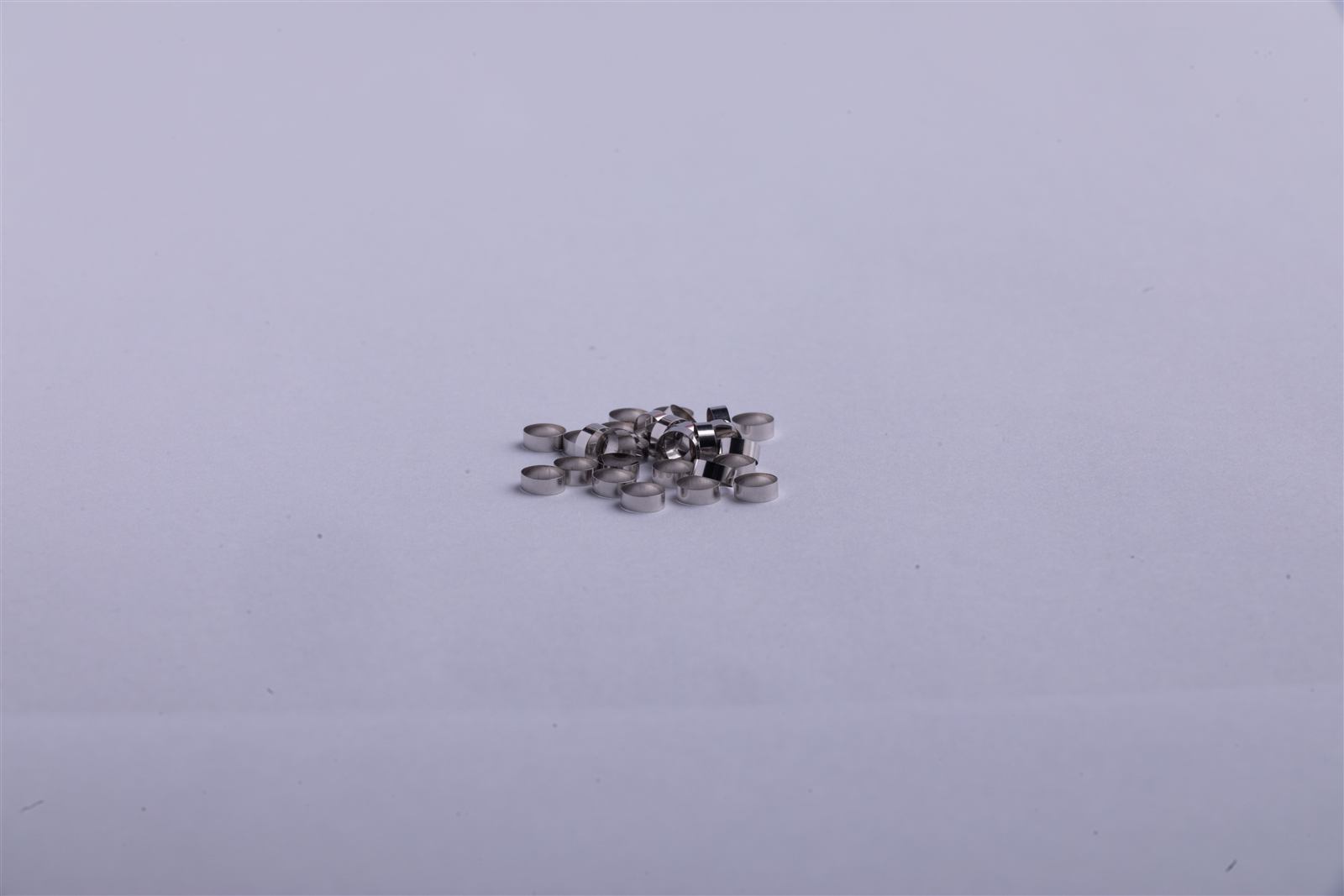
Where Thin Wall Platinum Iridium Marker Bands Fit
A thin-wall Pt-Ir marker band is a short radiopaque sleeve. It provides a position reference under X-ray or fluoroscopy when built into a catheter or delivery system. A thinner radial wall can help the marker fit within a tight outside profile, particularly when a polymer jacket covers the band.
The device team should check visibility on the finished assembly under representative imaging conditions. Band length, wall thickness, alloy and the surrounding assembly all affect the visible marker. See the platinum-iridium marker band family for standard and custom formats.
How to Specify Wall Thickness and Shaft Fit
For a concentric band, nominal radial wall thickness is (OD − ID) ÷ 2. For example, MOOSEN lists a 0.50 mm OD × 0.45 mm ID × 0.80 mm long band. Its nominal wall is 0.025 mm (25 µm). Use the example to check the geometry and ask about availability for your required dimensions.
Check assembly clearance using the smallest permitted band ID and largest permitted shaft OD at the marker station. Then check the largest band OD against the space available in the finished assembly. If minimum local wall matters, specify it separately and agree how to verify it. Nominal diameters describe the nominal wall, while eccentricity can make individual areas thinner.
Thin-Wall Band Drawing Specifications
| Drawing field | What to specify |
|---|---|
| Inner diameter (ID) | Nominal bore and tolerance. Include the mating shaft diameter and tolerance at the marker location, plus any coating present during assembly. |
| Outer diameter (OD) | Maximum band OD and maximum finished assembly OD if a jacket or encapsulation covers the band. |
| Wall thickness | Nominal radial wall and any separately controlled minimum or maximum. State how and where local wall thickness is measured if it is critical. |
| Axial length | Nominal length, tolerance and position relative to adjacent shoulders or other shaft features. |
| Pt-Ir alloy | Required composition and material specification. MOOSEN lists Pt90Ir, Pt80Ir and Pt75Ir for its marker band family. Confirm the grade for the selected geometry. |
| Edge and inspection criteria | Identify the bore edge, outer edge and end faces that require inspection. Specify the records you need with the order. |
Assembly and Inspection Considerations
Catheter shaft markers
Identify the exact shaft station where the marker will sit. A reduced shaft section, coating or shoulder can change the fit or axial space. Include how the band is held and whether it will be covered. See custom catheter marker bands for placement and attachment considerations.
Delivery system markers
Provide the drawing of the assembled distal section when the marker sits next to a tip, sleeve or other feature. Specify the maximum assembled profile and where the marker should appear relative to that feature during imaging.
Dimensional and edge inspection
MOOSEN lists appearance, dimensional and material inspection reports for its Pt-Ir marker bands. Share any requirements for local wall checks, measurement method, sampling, lot identification or packaging with the RFQ so they can be reviewed for the order.
Thin-Wall Marker Band FAQs
What is the minimum wall thickness I can specify?
MOOSEN lists a 25 µm nominal wall example in its marker band catalog. Ask us to review your target ID, OD, length, alloy and allowable variation together. The feasible wall depends on that combination.
Can I control both shaft fit and minimum local wall?
Yes. Mark the bore tolerance and the minimum local wall as separate acceptance criteria when both affect the assembly. Include your preferred measurement method or ask MOOSEN to review it with you.
How should I check radiopacity after reducing the wall?
Evaluate prototype bands in the finished assembly under representative X-ray or fluoroscopy settings. Compare the marker with your device-level visibility criteria before finalizing the drawing.
Can I request a standard size for prototyping?
Share the target dimensions and quantity. MOOSEN can check whether a listed size fits your trial or whether the geometry calls for a custom review.
Set a Radial Space Budget Before Specifying the Band
Start with the maximum assembled outside diameter at the marker location. Subtract the parts of that envelope already occupied by the shaft and by any outer layer that will remain in the finished device. Then identify how much space is available to the metal wall on each side of the shaft. Record whether the limit is a design target or an acceptance limit. The distinction helps the supplier see which dimensions have flexibility when reviewing a drawing with a very small wall.
The shaft itself may have a diameter range. The worst-case combinations for fit and external profile can differ. For example, the largest shaft affects entry into the bore, while the largest marker outside diameter may govern fit into an adjacent feature. Include the relevant limits even when the nominal sizes seem compatible. If the mounting region is recessed, add its axial depth and length and point to the specific drawing section that shows the installed band.
Define Minimum Wall and Diameter Controls
For a centered tube, nominal wall is half the difference between nominal outside and inside diameters. This arithmetic describes the ideal cross-section. A real component can have local variation around its circumference, so a minimum wall requirement needs a clear definition. If the wall at any point determines acceptance, identify the area to be measured and whether you require an agreed minimum in a particular section or along the full part. Review any edge breaks that affect where a valid reading can be taken.
Consider which dimensions can be used as reference values. A drawing that independently limits bore size, outside diameter and wall thickness should make the priority and acceptance method clear. If the component also needs controlled ovality or concentricity between mounting and external surfaces, name the relevant characteristic and datum rather than using a general request to make the band uniform. Discuss feasibility for the full tolerance combination with MOOSEN before requiring it on repeat orders.
Protect the Edge and Shape During Installation
A narrow metal edge near a shaft transition can influence how smoothly the marker travels into its final position. Show which edge contacts the shaft first and which face locates against the next component. If your design requires deburring or an edge break, define the requirement for the functional surface and how your team intends to verify it. Keep any different treatments at the inner and outer edges distinguishable on the print.
For a proposed attachment process, explain how the thin wall is supported while it is moved into position and held on the shaft. Record the mating part material where it affects the interface. Consider checking the marker before and after assembly during prototype evaluation, since the component drawing and the assembled outer profile describe different conditions. You can use the findings to refine the drawing callouts that control fit and to determine whether the quote should include specific handling or inspection arrangements.
Compare Visibility With the Finished Profile
Reducing metal thickness changes the material available to attenuate X-rays at a given marker location. Axial length, alloy, placement and the surrounding materials also influence the image. Compare prototype designs under conditions representative of the intended finished device, with the position and geometry of the candidate bands documented. An alloy name or a catalog wall example alone cannot determine the result for a particular catheter assembly.
If the visual task is to mark the ends of a working region, note the intended separation of the marker locations and which end uses each configuration. If the visual task is to make a particular assembly feature distinguishable from adjacent parts, capture what happens when it is viewed from the relevant angles. For teams comparing the relative merits of closed bands, marked segments and alternate marker shapes, the radiopaque marker selection page outlines the differences in geometry and placement.
Specify the Inspection Evidence You Need
Two teams can interpret a thin-wall drawing differently if the print does not define the measurement approach. Tell the supplier whether you need diameter readings, an agreed minimum local wall check, visual edge inspection or a combination. Include sample size or reporting frequency only where your quality plan requires one. A measurement instruction should describe the feature, the units and the expected report, while leaving the supplier room to propose a suitable method for the actual geometry.
For prototypes, capture the band revision and any changes arising from the fit trial before placing a repeat order. When a revision reduces wall thickness or changes an edge requirement, confirm whether earlier samples and drawing records need to be distinguished from the new build. A request for production quantities should include the intended lot identification and any applicable dimensional records. Review quality and inspection information when preparing the documents for your own incoming inspection.
When the space constraint is axial as well as radial, share both limits in the same request. For a longer hollow part, MOOSEN can assess cut marker tube geometry separately. For a band that needs a slot, hole or access around a larger feature, point it out on the assembly drawing before sizing the wall. The functional difference can affect where thickness control is critical and how a sample should be measured.
Check the Fit of the Trial Lot Before Releasing the Drawing
When a new band is first trialed, identify the shaft revision, the band lot and the order in which the parts are assembled. If your team sees a fit issue, record whether it occurs at initial entry, along the mating region or when the band reaches its intended location. Each observation points to a different part of the drawing. Include photographs or measured characteristics with your follow-up request when they help explain the issue.
For the next iteration, distinguish a dimensional correction from a change to the design intent. Adjusting a nominal bore while keeping the same functional clearance is a different request from changing which surface supports the band. If the design also requires changes to packaging or inspection, send those requests along with the revised print. A clear record of the trial helps engineering and sourcing evaluate whether the next sample answers the open questions before a production order is released.
Request a Thin-Wall Marker Band Quote
Describe which dimensions control fit and finished profile. Include the sample quantity and anticipated production quantity if available. To attach a drawing, use the RFQ form with file upload.
- Drawing revision and units
- Alloy, ID, OD, wall thickness and axial length
- Mating shaft dimensions, attachment method and required inspection records