
Precision Precious-Metal Components
Platinum Iridium Perforated Marker Bands
MOOSEN manufactures platinum iridium perforated marker bands to customer drawings for medical device assemblies. Each band combines a radiopaque platinum-iridium alloy with openings in the ring wall. Send us your drawing, mating dimensions and target quantity so we can review the band geometry, hole pattern and edge requirements for your project.
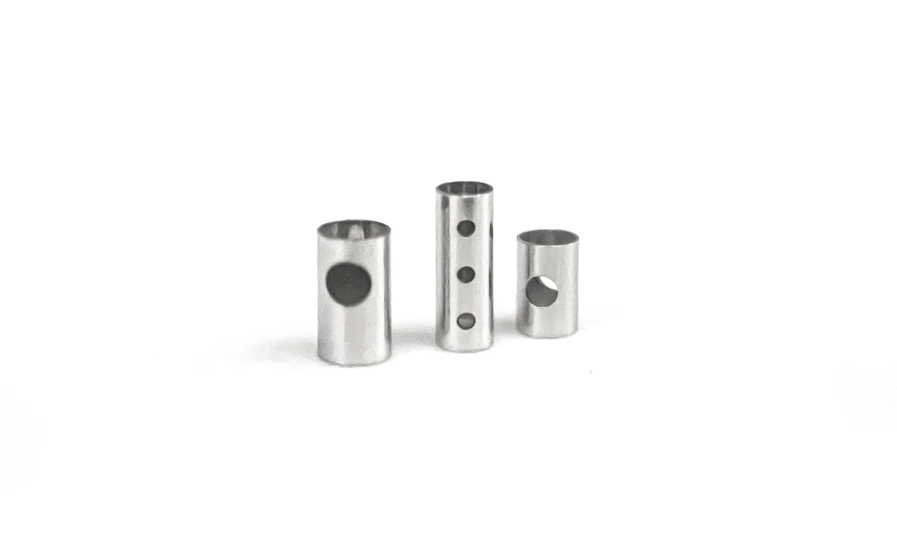
Pt-Ir alloy selection · Drawing-defined hole patterns · Dimensional inspection requirements
What Are Platinum Iridium Perforated Marker Bands?
A perforated marker band is a short ring with one or more openings through its cylindrical wall. The band fits around a shaft, tube or another mating component. In a device designed for X-ray or fluoroscopic imaging, the platinum-iridium band can provide a reference for locating a defined point on the assembly.
The openings serve the purpose specified by the device design. A drawing may call for a hole to align with a local feature or place an opening at a specific point around the shaft. That requirement makes the hole location part of the assembly interface. Two bands with identical diameters and length can fit the same shaft and still align differently with the mating part.
Use the finished assembly to define what the band needs to do. The device team can assess the visible marker profile under representative imaging conditions, including the effect of the pattern, band dimensions and orientation. If your design calls for a continuous wall, start with platinum iridium marker bands.
Hole Pattern and Assembly Fit
Bore and outside profile
Start with the shaft or mating diameter at the exact station where the band sits. Include the tolerance on that feature and the condition in which the band will be fitted. A coated shaft or a locally reduced section can have a different fit diameter from the rest of the component. If a jacket covers the band, provide the permitted finished profile as well as the outside diameter of the loose band.
Specify the band length along its axis. Where placement is critical, show how that length relates to the adjacent features on the assembly drawing. A band that sits between two shoulders, for example, needs a length that works within the available space across the permitted tolerances of all three features.
Hole size, spacing and position
Provide the hole count, opening size and location on the ring wall. Show the distance from the hole center or edge to the relevant end face. For multiple holes, specify the spacing or angular positions and identify the viewing direction. Use a dimensioned end view or developed view when the pattern is difficult to read on a side view of the cylinder.
The hole pattern also determines how much metal remains between openings and at the ends of the band. A larger opening in the same location reduces the distance to the nearest edge. Review these dimensions together, especially for short bands or designs with several closely spaced holes. If the drawing uses a minimum remaining wall section between openings, include it as a separate requirement.
Orientation and edge condition
If a hole must face a particular direction after assembly, show the reference feature used to set that angle. A drawing can identify the angular relationship to a shaft feature, a flat or another opening. For a repeating pattern, specify which positions are interchangeable so that the inspection criteria reflect what matters during assembly.
Call out the condition required at the band ends and around the openings. The inner edge of a through-hole matters when the bore slides over a shaft. The outer edge matters when the band sits under a thin covering or near a mating feature. Where a defined break edge or burr limit is needed, identify the surfaces it applies to and how it will be checked.
Drawing Specifications
Use the fields below to prepare a drawing or compare a quotation against your assembly requirements. Feasibility depends on the complete combination of alloy, band dimensions, hole layout and acceptance criteria.
| Specification | What to provide |
|---|---|
| Alloy grade | Required platinum-iridium composition and any material specification on the purchase drawing |
| Inner diameter (ID) | Nominal bore, tolerance and condition of the mating surface |
| Outer diameter (OD) | Nominal outside diameter and any limit that controls the finished assembly profile |
| Wall thickness | Nominal wall and any independently controlled minimum or maximum |
| Axial length | Band length, tolerance and end-face requirements |
| Openings | Shape, size, count, spacing and distance from the band ends |
| Hole orientation | Reference datum, viewing direction and angular tolerance where applicable |
| Edge condition | Requirements for the bore, band ends, outside surface and hole edges |
| Inspection state | Dimensions to verify on the loose band and requirements to assess after assembly |
| Order documentation | Required dimensional records, material documentation, lot identification and packaging |
Use one unit system across the part and mating drawings. Where inch and metric values appear together, identify the controlling units. If ID, OD and wall thickness are all independently toleranced, check that their limits can be met together. State which dimension controls fit and which controls the assembled profile.
Custom Band Review for Your Project
Share a dimensioned drawing and the relevant area of the assembly. For an early design, a sketch can show the intended hole pattern and fit, along with the dimensions your team is still evaluating. Identify the features with room for adjustment so the review can focus first on dimensions that determine whether the band can be assembled and inspected.
If you are sourcing an existing part, include the current revision and any approved changes. A reference sample can help communicate details such as edge condition or finish. Use the controlled drawing and written acceptance criteria to define the geometry for the quotation and the release of ordered parts.
For a prototype, identify the decision the first quantity will support. A team comparing two hole layouts may need samples by revision, while a team checking interference may need one geometry with measured ID and OD. Include the expected production quantity separately so the quotation can address the sample order and production requirements.
Applications in Catheters and Delivery Systems
Catheter shaft markers
In a catheter project, the marker may sit at a defined point on the distal shaft. Share the diameter at that station and describe the attachment method. If an opening needs to align with an underlying feature, identify its position relative to both the shaft and the band ends. See custom catheter marker bands for more on shaft fit and attachment requirements.
Delivery system position markers
A delivery system can use a band as a radiopaque reference at a specified position. Show the intended location on the assembly drawing. If the band touches adjacent parts or sits under an outer layer, include the available axial space and the maximum assembled profile. The device team can then plan imaging evaluation around the assembled configuration.
Compact medical device assemblies
A perforated ring may fit an assembly with limited radial space and a defined opening in the band wall. Share a section view showing the surrounding components and the opening’s intended relationship to them. Where the design calls for other Pt-Ir shapes in the same assembly, see our platinum iridium precision components.
Inspection and Order Documentation
Identify which dimensions determine acceptance before requesting a quote. Typical items to discuss include the bore and outside diameter, axial length, hole size and location, and the visible condition of the hole edges. A hole may meet its size limit but still miss its mating feature if the position is outside tolerance. List those requirements separately on the drawing.
Agree on how the important features will be measured. For a short band with small openings, show the end face or other feature used as the measurement reference. If a dimensional report is required, identify the characteristics to record and discuss sampling or part-by-part reporting when reviewing the order.
Tell us which material documents, lot identifiers and packaging labels your receiving team requires. For sample orders with several revisions, request separate labels so your team can match the parts to their drawings and evaluation records. Specify any special handling or packaging needed to protect thin walls or small openings during transit.
What to Include in Your Quote Request
Send the current part drawing with revision and units. Mark the required alloy grade, ID, OD or wall thickness, axial length and hole pattern. Include the mating dimensions that control fit and note the intended attachment method. A section view of the interface is useful when the assembly requirement is difficult to describe in words.
Provide the requested prototype quantity, expected production quantity and target date. Include the inspection records, documentation and packaging your team needs. If purchasing and engineering are working from different revisions, confirm the version for quotation before submitting the request.
Frequently Asked Questions
Can a drawing labeled “perforated ring” be used for a marker band inquiry?
Yes. Submit the drawing under its existing part name. The drawing should identify the function, finished ring dimensions, openings in the wall and any fit requirements. That information provides a shared reference for engineering and purchasing.
Can MOOSEN quote a hole pattern from a sketch?
A sketch can support an initial discussion when it shows the approximate dimensions, hole count and assembly interface. Include any dimensions your team has already fixed. For an order, confirm the controlled drawing and the tolerances the supplied components must meet.
What hole size or positional tolerance should I specify?
Base the requirement on the mating feature and allowable misalignment. Send the nominal pattern together with the band wall, alloy grade and dimension that controls hole location. Feasibility can then be reviewed for the complete geometry. For drawings with several critical openings, indicate which ones govern assembly.
Are perforated marker bands available from stock?
Perforated bands with drawing-specific hole patterns are reviewed as custom parts. Send the part dimensions, alloy and quantity to confirm feasibility and availability. For enquiries about a standard band with a continuous wall, include your target ID, OD or wall thickness, and length.
Can we request material and inspection documentation?
Include the required documents in your inquiry. Examples include material composition records, dimensional inspection results and lot identification. Specify any required format or sampling plan so the documentation scope can be agreed with the order.
Does the hole pattern affect how the marker appears under imaging?
The size and position of the openings change the distribution of metal in the band. The resulting image also depends on the band dimensions, orientation and surrounding assembly. Evaluate the marker on the assembled device under the imaging conditions defined by your test plan.
Request a Quote for Your Perforated Marker Band
Send your latest drawing, mating dimensions and target quantity to MOOSEN. Include the feature your team needs to confirm first, such as an opening that must align with the shaft or a radial profile limit beneath the outer jacket. We can use those details to review fit, hole geometry and inspection requirements for the quotation.