
IMPLANTABLE CONNECTION COMPONENTS
Medical Hermetic Feedthrough Assemblies
MOOSEN manufactures customer-designed miniature hermetic feedthrough assemblies. A specified assembly can combine a titanium-alloy housing, alumina ceramic insulation and Pt–Ir conductors; geometry and acceptance testing follow the approved design.
What this component does
MOOSEN can supply the specified sealed feedthrough assembly as well as individual terminals and conductors. MOOSEN and the buyer agree assembly-level inspection and leak-test requirements; the device maker remains responsible for final system qualification.
The final form, material condition and acceptance criteria are agreed against the customer’s specification.
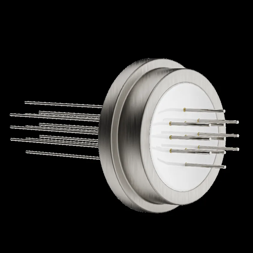
Specification fields for engineering review
The table defines information to provide in an RFQ. It is not a published stock-size or performance claim.
| Interface type | Single terminal, multi-contact or connector-related geometry |
| Conductor | Material, form, spacing and electrical interface by drawing |
| Insulator or housing | Titanium-alloy housing and alumina ceramic insulation where specified; seal boundary per approved drawing |
| Geometry | Pin dimensions, pitch, orientation and location tolerances |
| Joining | Braze, weld or other joining route to be reviewed for the project |
| Qualification scope | Assembly inspection, hermeticity and electrical tests agreed for the specific product |
Design questions to resolve early
Seal boundary
Identify which component surfaces form part of the hermetic boundary and which party validates the assembly.
Electrical spacing
Define conductor count, isolation and mating geometry before detailed manufacture.
Inspection access
Plan measurement and records for critical dimensions and joining surfaces.
Why choose MOOSEN for feedthrough components
- Existing MOOSEN connector and single-seal terminal pathways
- Engineering alignment of conductive parts with customer-specified ceramic interfaces
- Component records agreed to the project specification
Select the right component for your assembly
Compare feedthrough bodies and conductors by the electrical path and the package seal they serve. Review each feedthrough with its conductor connections and the housing joint the component will meet. The feedthrough drawing and test boundary define which conductors, seals and joints are reviewed for this order.
| Component route | Choose it when | What to confirm |
|---|---|---|
| Medical hermetic feedthrough components | an electrical pathway across a specified sealed boundary | Use the approved drawing and assembly method as the decision basis. |
| Hermetic single seal terminals | a single-channel terminal architecture is needed | Review this component |
| Hermetic rectangular connectors | a rectangular multi-channel package is needed | Review this component |
Prepare a useful RFQ
Send the housing section with its revision and mark the conductor layout and the component test boundary. The contact form accepts the enclosure section, circuit map and component-level leak-test scope with the quantity needed for review.
- channel count
- package envelope
- Pt–Ir conductor interface
- seal boundary
- mating connection and test method
Evidence to agree: the feedthrough body and pin materials, pin position, insulation measurements and leakage results for the defined boundary. The allowable seal and conductor dimensions follow the specified housing and the agreed feedthrough checks.
Define the Feedthrough Boundary on the Housing Drawing
A medical hermetic feedthrough passes electrical conductors through a housing wall while maintaining the defined sealed boundary. A drawing should show where the feedthrough body meets the housing, where the insulator separates the conductors and which surfaces the OEM will join during assembly. Call out the dimensions that locate the feedthrough relative to the housing datum and identify which faces remain accessible after closure.
For a welded or brazed assembly, identify the joint addressed by the component RFQ and any separate housing joint that will be made later. A leak check on the feedthrough can cover the conductor seals and the feedthrough body within its fixture. An enclosure-level check can cover additional interfaces after installation. Show both boundaries when the drawing covers more than one stage so the test report and inspection criteria can be matched to the actual supplied part.
If the design uses a removable external connector, document both the mating side and the housing interface. A seal around a retained fitting needs separate definition from the geometry of the removable plug. For an overview of those choices, see circular and bulkhead connector formats once the relevant mounting and service requirements are known.
Arrange Pins and Terminations for the Intended Connections
Create a contact map before finalizing the pitch. Number each position against a defined view and identify spare, unused or shell-bond positions explicitly. Specify contact dimensions, the intended PCB, wire or mating connector interface and the required projection on each side. If a pad or solder joint constrains the rear clearance, show its maximum envelope alongside the conductor layout.
For a wired feedthrough, identify where each conductor exits, the orientation, workable lead length and connection method. Plan which stage will verify wire identification and continuity. For a feedthrough with pins, define the pin measurement plane and the allowable position relative to the locating surfaces. Give both edge clearance and pitch constraints if the assembly depends on both. A pin count by itself tells a supplier little about the layout or the resulting dielectric geometry.
When a project needs only one isolated circuit path, compare the assembly interface of a hermetic single-seal terminal. Where the housing opening or contact layout is rectangular, review the rectangular connector mounting and terminal requirements. Keep the related format aligned with the intended seal boundary and the actual conductor termination.
Identify Material and Electrical Requirements Together
Specify the body, insulator and conductor materials by the project’s accepted designations. If a surface coating, plating or material finish is required, mark the surface it applies to. Include any downstream joining conditions that affect the assembly. The combination of pin material, insulator and body is important during review because these features cooperate mechanically and electrically at the sealed interface.
When setting the electrical acceptance criteria, identify which circuits will be tested to each other and which will be checked against the housing. State the applicable continuity, insulation resistance or dielectric withstand requirement and the conditions under which it is to be measured. For an assembly with different circuit classes, specify each applicable requirement on the contact map. The selected layout then has a clear relationship to the intended test points.
Some programs source a sealed feedthrough assembly, while others order conductors or terminal components for their own package process. State which item you need quoted and which operations your facility will complete. This prevents an order for individual conductor features from being interpreted as an order for a tested sealed component. Related contact interfaces are explained in implantable connection components.
Make the Leak-Test Requirement Measurable
Include the maximum leak rate, units and the approved method in the RFQ where a leak test is part of the supplied scope. Specify the gas basis, test pressure or differential, direction and any timing or conditioning required by the procedure. When the test covers a defined side of the part, include the fixture orientation and a drawing view of the boundary. A numeric value without a test setup can make a supplier quotation difficult to compare with the receiving specification.
Consider the inspection stages together. If a component is checked before it is welded into the final package, agree how the result will be identified and how the OEM will test the installed enclosure. An assembly process can introduce interfaces that were absent during component testing. If the final package must be tested after thermal cycling or other qualification exposures, document that requirement separately and identify who performs it.
For reports used to release parts, confirm whether readings are required by serial number, by lot or for an agreed sample. Identify the required fields, limits and revisions. A process trial can help determine whether the proposed fixture and sensitivity work for a new geometry before the buyer specifies final acceptance. Ask MOOSEN which component-level checks are included in the quote and record the agreement on the purchase documentation.
Prepare the First Article and Production File
Identify the sample quantity and the questions it needs to resolve. Mechanical fit, contact accessibility, electrical testing and leakage can each require a different setup. Provide a mating part drawing or reference fixture when it is essential to the fit check. Where the first sample tests a new pin or seal arrangement, record the part revision and identify which housing or fixture was used for the result.
For recurring orders, state the documentation needed for receiving. Where applicable, include material identification, critical dimensional measurements, electrical results, the leak-test record and lot identification. Ask how those records link to the assembly or shipment. Review MOOSEN quality and inspection information to prepare the checks and records relevant to the component.
Make open design questions visible in the request. For example, the external mating face may be fixed while an internal terminal can change to improve assembly access. The request should make clear which constraint cannot move, which option is a candidate and how the next sample will be accepted. The same drawing package can then support engineering review, an initial quote and the inspection plan when the design is released.
Frequently asked questions
Can MOOSEN provide a feedthrough to a drawing?
Yes. Send the assembly drawing, material stack, channel count and target leak and electrical tests. MOOSEN can quote the specified feedthrough assembly or individual parts.
Is a hermeticity value guaranteed here?
No universal leak-rate or electrical rating is claimed. Acceptance criteria must be agreed for the specific design and verified by the responsible parties.
What should an RFQ include?
Share conductor count, geometry, materials, joining method, sealing boundary, inspection criteria and forecast quantity.
Can terminal count and pitch follow our package drawing?
MOOSEN quotes drawing-defined conductors and terminal features for the specified count, pitch and mating interface after a manufacturability check.
Can we receive parts for a seal-process trial?
MOOSEN can supply feedthrough assembly samples or agreed parts for the buyer’s package and seal-process evaluation.
What test requirements should be included in the RFQ?
Provide the package drawing, material system, target leak test, electrical requirements and inspection records. MOOSEN will state which component-level checks are included in its quotation.
Review your medical hermetic feedthrough components drawing
Send the drawing, application, prototype quantity and required records. MOOSEN will review the component scope and respond with the information needed for quotation.