
MEDICAL SENSOR COMPONENTS
Medical Temperature Sensors and Thermocouples
Medical-device temperature sensing requires a defined measurement location, junction construction and integration method. MOOSEN manufactures customer-defined temperature sensors and fine sensing leads, including thermocouple constructions, with lead routing, connection and inspection specified for the application.
Start with the measurement and environment
Catheter and device developers need the sensing junction to fit the intended geometry while leaving room for insulation, joining and verification. The measurement system and finished-device performance are validated by the device maker.
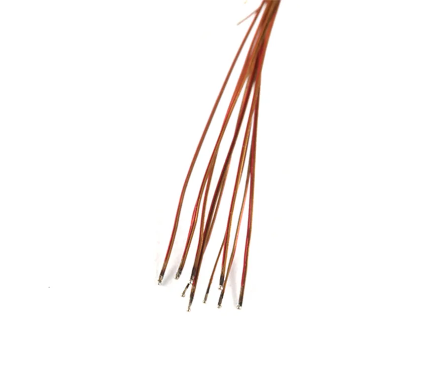
Three design decisions
Where is temperature measured?
Mark the intended sensing point and nearby material stack on the drawing.
How is the junction protected?
Define contact with fluid or tissue, insulation and strain relief around the junction.
What must be tested?
Set component acceptance criteria and system validation responsibilities before release.
Project specification checklist
Use these fields to define the proposed component. Numerical requirements are agreed per project and verified by the customer’s method. If the design uses a color-coded extension cable, record the identification standard. The thermocouple wire color code chart compares common ANSI/ASTM and IEC conductor markings by polarity.
| Sensor principle | Thermocouple, NTC or RTD construction as specified for the product |
| Junction | Location, exposed or protected form, and joining method |
| Wire | Conductor material, diameter, length and condition |
| Insulation | Material, wall, coverage and interface to the device |
| Response requirements | Target environment and measurement method supplied by customer |
| Verification | Continuity, dimensional and other agreed component checks |
MOOSEN support from drawing to component
- Coordinate the sensing element, conductor and interface requirements in one engineering plan
- Discuss material, miniature feature and assembly constraints before sampling
- Agree inspection points and documents for each component order
Select the right component for your assembly
Compare the junction, lead and readout interfaces when selecting a temperature-sensing component. Choose the sensing construction that matches the intended measurement location and instrument input. The feasibility review uses the sensing-point drawing, lead routing and operating conditions.
| Component route | Choose it when | What to confirm |
|---|---|---|
| Medical temperature sensor components | a temperature junction and signal path defined by the measuring location | Use the approved drawing and assembly method as the decision basis. |
| Ultra-fine medical sensor components | miniature size and routing dominate the design | Review this component |
| MRI-compatible temperature sensors | temperature sensing is required in a strong electromagnetic or MRI environment | Review this component |
Prepare a useful RFQ
Include the sensor drawing revision and identify the junction geometry, lead dimensions and instrument interface. The contact form accepts the sensing-point drawing, lead routing and any verification records needed at the sample and production stages.
- measurement point
- junction geometry
- conductor
- protection
- routing
- calibration and test method
Evidence to agree: the sensing alloy identity, junction position, conductor polarity and calibration checks stated in the lead specification. Sensor dimensions and verification depend on the sensing environment and the assembly construction.
Specifying thermocouple wire for medical applications
Start with the part you need to purchase. If your team forms the measuring junction, the order may call for separate thermocouple-grade conductors or a matched pair. If the junction arrives assembled, the drawing should identify the sensing point, lead route and termination. A third possibility is a cable that connects a finished sensor to the instrument. Each part has different acceptance criteria, even when all three belong to the same temperature measurement channel.
MOOSEN manufactures customer-defined sensing leads and assemblies. For a feasibility review, share the mechanical drawing and name the thermocouple type required by the readout. Type J and Type K use different alloy pairs and voltage curves, while Type S uses a platinum-rhodium and platinum pair. The thermocouple type helps define the electrical specification. The wire diameter, insulation, junction and termination still need to be specified for the assembly. See the guides to Type J and Type K thermocouple wire and Type S thermocouple wire.
Wire constructions for thin sensing leads
When comparing constructions, check whether the diameter on a drawing refers to bare metal, one insulated conductor or the outside dimension across the pair. A slot designed around bare-wire diameter may be too narrow after insulation and assembly. On the drawing, show the space available around the junction, the clearance at the tightest point along the route and the area available for strain relief at the termination.
Bare thermoelements and individually insulated pairs
Bare thermocouple-grade legs suit designs where the surrounding assembly provides separation and protection along the intended route. Identify the material and polarity for each leg and specify how they stay separate up to the junction. Individually insulated legs allow the conductors to run together through a compact route. Specify the maximum finished diameter of each leg and the combined envelope. If the conductors emerge at different points for joining or termination, dimension the exposed length of each one.
Paired leads and finished sensing assemblies
For a paired lead, show whether the conductors lie side by side or follow a twisted route, and dimension any added jacket or sleeve where it changes the finished profile. For an assembled lead, dimension the junction, the location of any support or strain relief and the position of the final terminal. Clarify where bending is expected during installation or use. If your design includes separate fine conductors or other miniature parts, see ultra-fine temperature-sensing lead components.
Junction placement and the temperature budget
Put the intended measurement point on the drawing and show the junction relative to the surface, enclosure or sensing volume. In a surface measurement, attachment pressure, contact area and any layer between the junction and the surface can change the reading. The wires also conduct heat away from or toward the junction. A lead that runs straight from the measuring point to a cooler support creates a different thermal path from one that follows the measured surface before leaving it. Compare prototypes using the planned mounting and routing. See Analog Devices on thermocouple installation errors.
List the normal, peak and minimum temperatures at the measuring junction, the first section of insulation, any splice and the instrument terminals. Also include transient conditions during assembly or processing if the lead sees them. This helps establish separate material limits for each zone. The thermocouple reference function defines the nominal voltage response, while the continuous and short-duration limits of the finished lead depend on the specified materials and construction. See IEC 60584-1 reference functions and tolerances.
Junction construction and response time
A small exposed junction can respond quickly when it couples directly to the measurement environment. An insulating layer, encapsulation or a protective sheath adds thermal resistance, thermal mass or both, depending on the design. If the junction contacts a conductive part, specify whether the measurement circuit requires electrical isolation at that point. Compare the response of complete prototypes, including the planned attachment, since the wire diameter alone gives an incomplete picture of the installed result.
Define the response requirement as a test. For example, record the time to reach 63.2% or 90% of a specified temperature step and identify which threshold applies. State the medium, the mounting method, the starting and final temperatures, and the air or liquid flow if relevant. Include the instrument settings when filtering or sampling affects the observed result. A response time measured in flowing liquid and one measured on a bonded surface describe different conditions. See OMEGA fine-gauge thermocouple response data.
Transitions, extension cable and reference junctions
You can design a short fine-wire section to reach the measuring point and use a more robust lead for the rest of the run. Mark where the conductor changes and record the temperature at that transition. Extension cable uses conductors of the same nominal composition as the matching thermocouple legs and has its own specified cable temperature range. Compensating cable uses other alloys selected to approximate the relevant thermoelectric response over a defined interval. Give both the cable designation and its required tolerance, and check the jacket rating separately for the route. See IEC 60584-3 for extension and compensating cables.
Mark both legs at every termination. Specify the color convention and pinout for connectors and harnesses, and use labels that remain identifiable after assembly. At a typical thermocouple input, the instrument measures the temperature where the thermocouple-compatible conductors meet copper. If you introduce copper earlier in the circuit, identify how the reference temperature will be measured at that transition.
Document the maximum lead length, the expected loop resistance and the input module used to read the signal. Very fine wires have higher resistance per unit length than larger conductors of the same material. That can matter on long runs or with inputs that use a current for open-wire detection. If the route passes through noisy electronics, include the intended shielding and grounding on the wiring diagram. Use the actual readout and lead length when qualifying a prototype. See Analog Devices thermocouple input design guidance.
Drawing and documentation for a quote
Send a dimensioned drawing or a marked sample showing the sensor tip, the insulation profile, strip lengths, lead routing and terminal details. State the requested alloy pair and tolerance, the finished length and the sample and production quantities. If the sensing leads and the cable have different specifications, identify them separately. Include the required inspection records, leg and lot identification, and any electrical checks that apply to the delivered part.
For thermoelectric verification, specify whether you need a lot-level material record or a calibration report for individual assembled sensors. Give the comparison points and acceptance limits where applicable. If your device needs to meet a temperature measurement tolerance after assembly, also state the intended installation and the system verification method. See ASTM E220 for comparison calibration.
Frequently asked questions
Can MOOSEN make a sensor to a customer drawing?
Send the sensor and device-interface drawings. MOOSEN will identify the relevant components, construction requirements and proposed supply scope.
Which thermocouple type should be used?
The device maker specifies the sensor principle and material system. MOOSEN develops the component manufacturing approach against that specification.
Do you claim finished medical-device accuracy?
No universal device-level accuracy is claimed. Calibration and finished-system validation depend on the customer’s design and test method.
Can the wire length and junction location follow our drawing?
MOOSEN quotes drawing-defined fine-wire and junction-related component geometry, including specified length and placement. The final assembly scope is confirmed with the buyer.
Can you support a prototype sensor build?
MOOSEN can supply the specified component samples for the customer’s thermal and assembly tests before repeat production is released.
How is temperature accuracy established?
MOOSEN supplies components to the agreed drawing and inspection criteria. Calibration and accuracy of the finished sensor are verified by the device manufacturer.
Send your sensor requirements
Include the application, sensor drawing, exposure or measurement conditions, prototype quantity and required test records.