
PRECISION METAL COMPONENTS · MEDICAL DEVICE SUPPLY
Platinum Iridium Precision Components
MOOSEN develops drawing-based Pt-Ir rings, marker bands, wire and custom contact components for medical-device programs. We bring material, geometry, assembly fit and inspection into one practical manufacturing review.
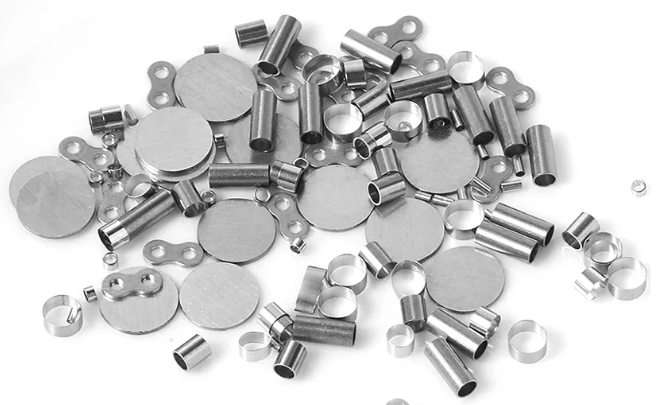
Precision component forms from the MOOSEN product portfolio.
Material and form
Pt-Ir wire, tubular rings and drawing-defined component shapes.
Built around integration
Geometry and surface condition reviewed with the mating device assembly.
Inspection planned early
Critical features and records agreed for the project.
THE CAPABILITY
Precision parts that connect material science to device design
Platinum iridium precision components can serve different roles within a medical device: a visible marker, a conductive contact, or a fine wire element. Each role calls for a different approach to geometry, surface condition and downstream assembly.

Manufacturing at the MOOSEN facility.
COMPONENT PORTFOLIO
Platinum iridium precision components by form and function
MOOSEN supports component development across several Pt-Ir forms. The links below lead to detailed product pages; this page shows how they fit into a broader device program.
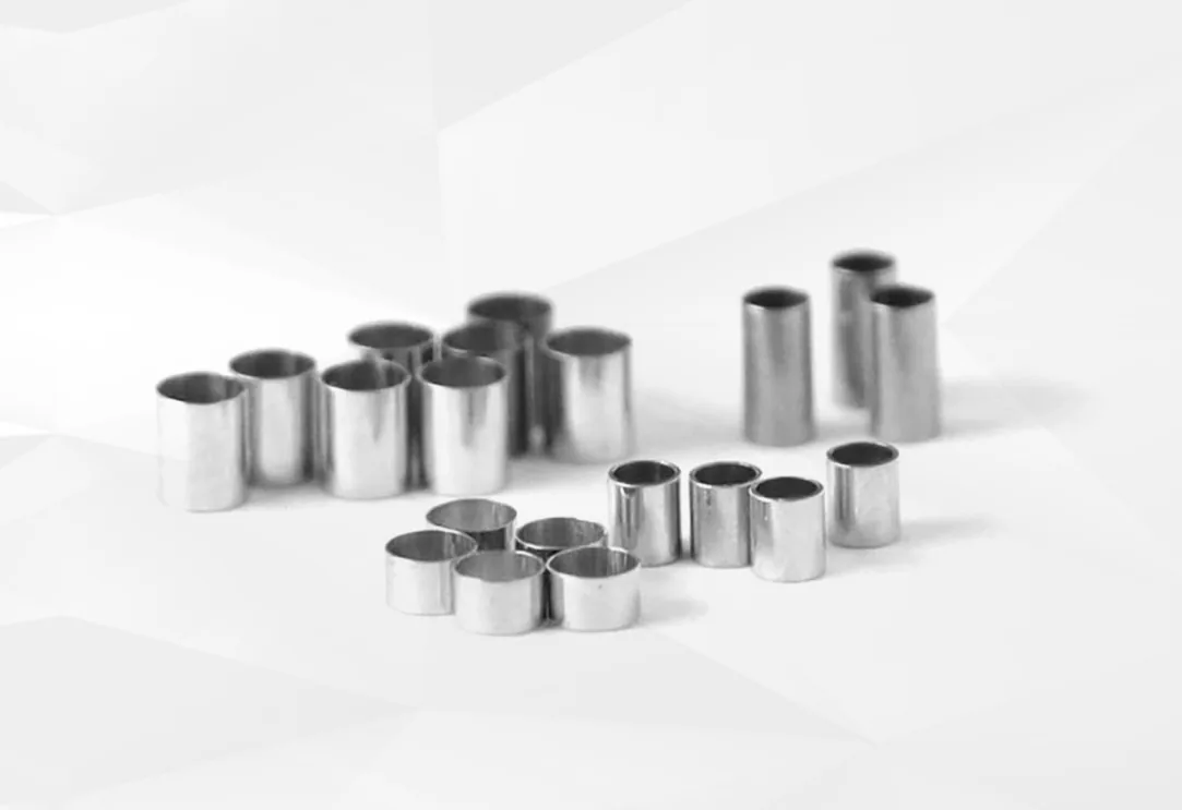
Radiopaque marker bands
Small tubular markers for catheter and delivery-system visibility. The drawing controls fit, edge condition and the intended attachment method.
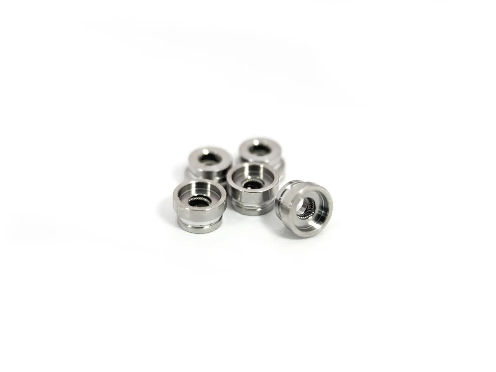
Electrode rings and contacts
Metallic contact features considered with the electrical interface, surface requirements and assembly method.
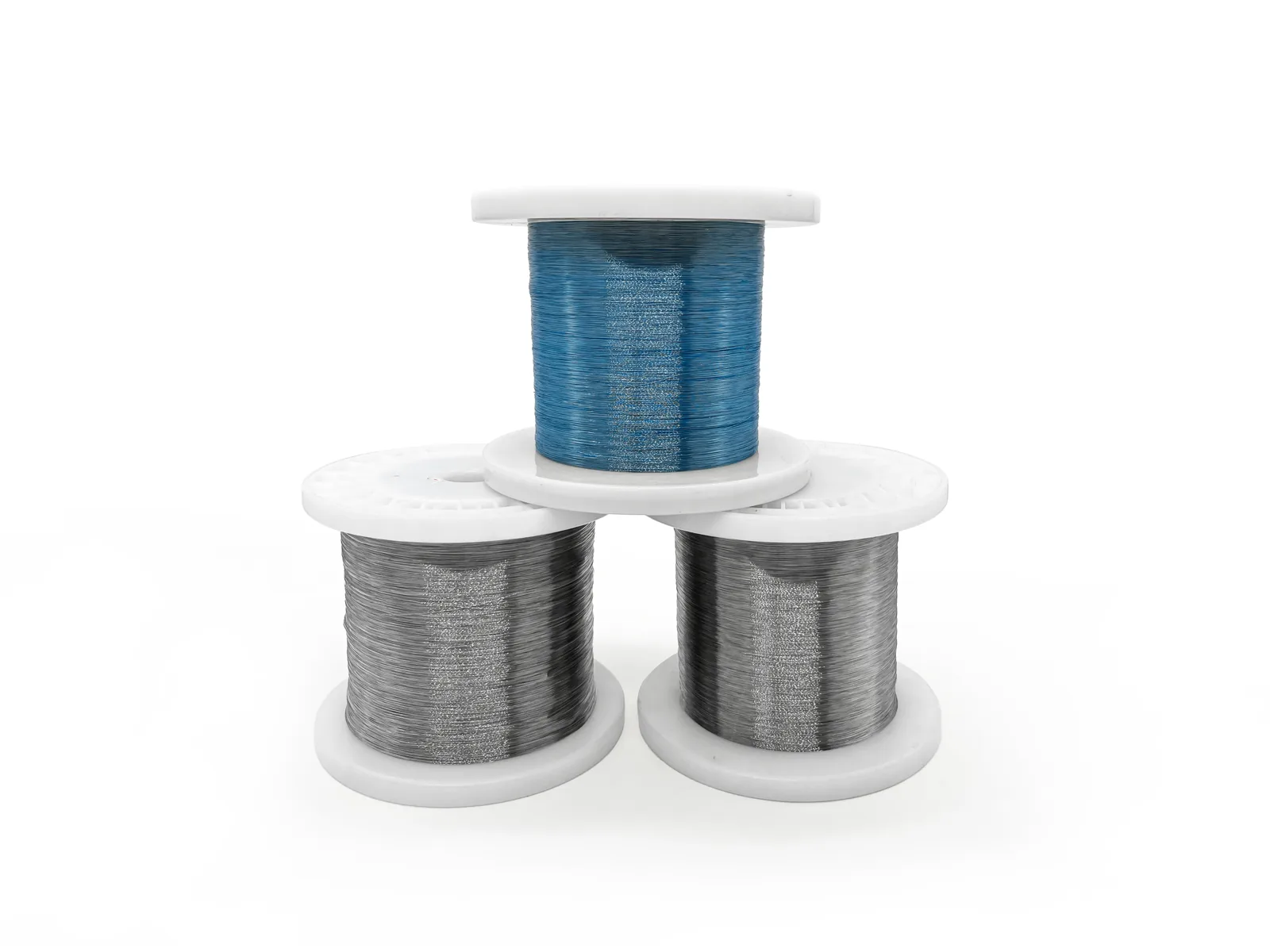
Platinum iridium wire
Fine wire supplied to the material and dimensional requirements of electrode, lead and connected-component programs. View fine wire grades and diameter tolerances.
ENGINEERING FOCUS
Made for the part that comes next
A precision component must integrate reliably with its mating assembly. MOOSEN engineers each metal part around the shaft, conductor, contact or other interface, then defines the manufacturing and inspection approach.
Drawing-defined geometry
Ring dimensions, wire form and special features follow the agreed design.
Surface and edge control
Finish and edge conditions are considered against the assembly and inspection method.
Material and process alignment
Alloy choice, forming route and component handling are evaluated together.
Project-specific records
Material, dimensional and release documentation can be planned around the approved requirements.
WHERE THE COMPONENTS WORK
Experience across interventional and electrode programs
MOOSEN’s component work spans marker and contact needs in customer-designed devices. These are examples of application areas, with final geometry and qualification determined by each device program.
Interventional device markers
Radiopaque rings and bands that help identify device locations under imaging.
Electrode interfaces
Conductive rings, contacts and wire elements for electrical connection in device assemblies.
OEM component integration
Drawing-based parts considered alongside the customer’s joining and assembly process.
Related project experience
An anonymized neuromodulation program involved spring wire and Pt-Ir ring components. In a separate interventional project, MOOSEN supplied Pt-Ir marker components.
MOOSEN supplies components for integration into customer-controlled devices; finished-device validation remains with the device manufacturer.

MOOSEN production facility.
MANUFACTURING & QUALITY
A visible process behind small components
Inspection supports the features that matter to the drawing and the assembly. MOOSEN combines manufacturing review, sample evaluation and appropriate dimensional or visual checks to support controlled component supply.

Microscope inspection at the MOOSEN facility.
01 · Engineering review
Material, function and device interface considered together.
02 · Process planning
Manufacturing route and critical features defined for the configuration.
03 · Sample evaluation
Early components checked against the agreed design intent.
04 · Inspection and release
Appropriate visual, dimensional and continuity checks, with records as agreed.
DRAWING-DEFINED SPECIFICATIONS
Specify a platinum–iridium component by its device function
For a custom Pt–Ir component, there is no meaningful universal size chart. These fields define the RFQ and the inspection plan; final values come from the approved customer drawing.
| Function | Radiopaque marker, exposed electrical contact or other defined interface |
| Material | Pt–Ir alloy grade, material condition and requested certification |
| Geometry | Drawing-defined form, critical dimensions, tolerances and revision |
| Surface and edge | Finish, edge condition and cleanliness requirements |
| Assembly interface | Mating part, joining method and process exposure |
| Verification | Inspection method, sampling, traceability and release records |
MOOSEN defines the manufacturing route and achievable tolerances against the component drawing and mating assembly.
COMMON QUESTIONS
Select the right component for your assembly
Compare adjacent MOOSEN component forms by function and interface. These are design routes, not interchangeable stock sizes. Final feasibility, dimensions and acceptance are reviewed against your drawing.
| Component route | Choose it when | What to confirm |
|---|---|---|
| Platinum–iridium precision components | a custom Pt–Ir part outside a standard band, ring or wire brief | Use the approved drawing and assembly method as the decision basis. |
| Platinum–iridium marker bands | a tubular radiopaque marker | Review this component |
| Platinum–iridium medical wire | the supplied form is fine Pt–Ir wire | Review this component |
Prepare a useful RFQ
Please include the current drawing revision and the fields below where available. The contact form accepts a drawing or specification file; prototype quantity, annual volume and required records can be added there.
- device function
- material condition
- drawing revision
- critical features
- mating part
- process exposure and verification
Evidence to agree: material documentation, critical dimensions, visual or electrical checks, sampling and release records as applicable to this component. No universal size, tolerance or performance claim is implied.
Select the component form from the assembly sequence
Start with how the metal part reaches its final position. A closed band typically needs access from one end of a shaft or a build sequence that places the shaft inside it. A slotted ring can suit a design that needs side access, angular registration or a clearance opening, depending on geometry. A disc or plate can seat against a ledge or pocket. For small parts with steps, tabs or holes, show how they are guided and held in place during the next operation.
Closed bands and slotted rings
For a closed band, show the largest feature the part must pass over and diameter of its final seat. An adequate fit at the seat can still leave an obstruction farther up the shaft. On a slotted ring, give the width and end profile of the slot and final position relative to the mating feature. When the gap changes during assembly, dimension the free and installed conditions separately. Review marker bands and marker rings for imaging-reference designs.
Discs, plates and small featured parts
For a disc or plate, identify the face that seats first, the face that remains accessible and direction of any bevel. Thickness matters where the part sits flush or leaves space for a layer. For a part with holes, flats or raised features, dimension them from the functional face or locating feature. Identify details that must stay accessible to tooling. For a conductive part around a shaft, consult the electrode ring interface requirements.
Make the retention and machining requirements inspectable
A shoulder controls seating depth, and a tab or flat can control orientation. If the design relies on a dimensional fit, state the relevant tolerances for both mating parts. If another process secures the component, mark the work area and surfaces that must stay clear. Include a cross-section where the installer cannot see the seating face in the final position. Refer to the applicable ASME drawing and tolerancing standards in the drawing package if used.
Review thin walls, narrow slots and internal corners against machining and inspection access. A bore needs enough access for the agreed method, while an optical edge check needs a clear line of sight. Distinguish a critical edge radius from a general deburring requirement. For a broad face, specify flatness or finish where it affects seating or joining. See NIST small-hole measurement research.
Keep features with a functional relationship together on the inspection plan. A plate may pass thickness and width checks and still sit above its intended position if a corner radius stops it from reaching the bottom of the pocket. Submit the section of the mating pocket and identify whether fit is judged by numerical measurements, a fixture or an assembly sample. Specify the evidence for each stage.
Specify evidence from prototype through repeat order
For feasibility, submit the part and mating geometry with the material callout, revision and quantities. Highlight assembly constraints that affect access or fit. For sample acceptance, agree which dimensions are critical, how they are measured and in which state. Link results to feature identifiers so the buyer can compare the sample with the drawing.
For a repeat order, specify material and lot records, packaging, identification and acceptance checks. When a drawing changes, name the revision and features that require new results. Include the position in the assembly, the retention method and planned processing after delivery. For electrical parts, see how the electrode components guide defines exposed surfaces and test requirements. Review MOOSEN quality information when specifying documents for receiving.
Platinum iridium precision component FAQs
What kinds of platinum iridium components can MOOSEN support?
The current portfolio includes marker bands, electrode rings or contact features, fine wire and other drawing-defined precision forms. Feasibility depends on the specific design.
Are these catalogue parts or custom components?
Most components are engineered to the customer’s drawing and intended device interface. Existing forms can provide a starting point for a new design.
Can MOOSEN support both component production and inspection?
MOOSEN defines the manufacturing route and project-specific inspection plan for the agreed component configuration. Available checks and records are confirmed before production.
Does MOOSEN supply finished medical devices?
No. MOOSEN supplies materials and components for customer-designed devices. The device manufacturer is responsible for finished-device validation and regulatory decisions.
Can several platinum-iridium part forms be sourced under one program?
MOOSEN can quote drawing-defined rings, marker bands, wire and contact parts as separate controlled items for the same device program.
Can you support prototype and repeat production orders?
MOOSEN can supply samples for the customer’s fit and process trials and manufacture repeat orders to the approved drawing and purchase specification.
LET’S TALK COMPONENTS
Develop the next Pt-Ir component with MOOSEN
Send your component drawing or performance requirements. MOOSEN will identify the suitable product form, manufacturing route and next engineering steps.