
Drawing-based Pt–Ir components
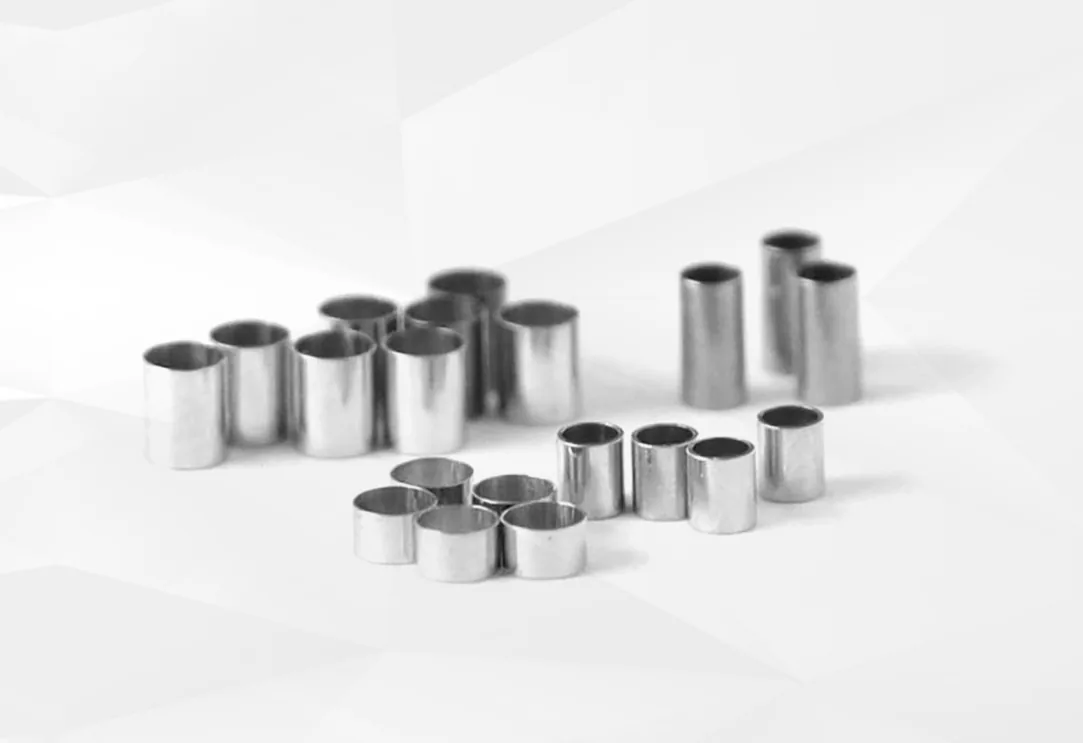
Platinum Iridium Catheter Markers
Platinum iridium catheter markers are radiopaque bands that identify a defined position on a catheter under fluoroscopy. MOOSEN manufactures custom Pt–Ir marker bands to customer drawings. Send your shaft diameter, target band dimensions and attachment method for a fit and inspection review.
Shaft fit
Fit the Marker Band to Your Catheter Shaft
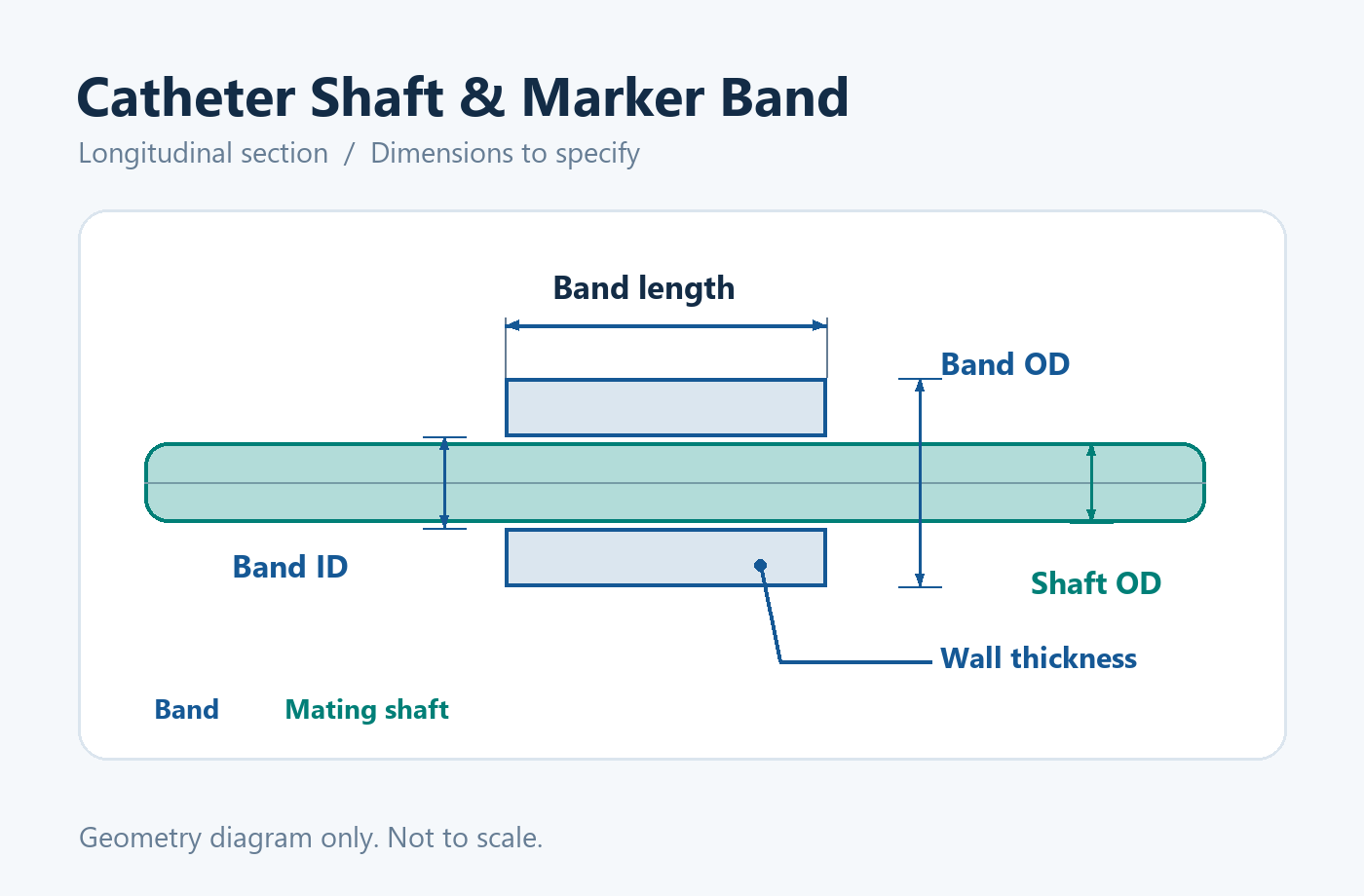
Start with the shaft OD where the band will sit and the maximum OD allowed after assembly. Specify the band ID, OD, wall thickness and axial length, then mark its position on the shaft drawing. For a low-profile assembly, see how to specify thin wall platinum iridium marker bands.
Identify the intended attachment method and any clearance needed for tooling. If the band sits under a polymer jacket, include the jacket thickness and the maximum finished profile in the assembly drawing.
Engineering review
Drawing Requirements for Custom Marker Bands
A useful drawing identifies the dimensions and tolerances that control fit. Mark which dimensions must pass inspection and include the current drawing revision.
| Drawing item | What to provide | What MOOSEN reviews |
|---|---|---|
| Mating shaft | Shaft OD at the marker seat, tolerance and installation position. | Fit between the shaft and band ID, assembly clearance and marker placement. |
| Band geometry | Target ID, OD, axial length and wall thickness. Mark the dimensions that control fit or acceptance. | How the dimensions and tolerances work together, including the maximum finished OD. |
| Alloy and condition | Required Pt–Ir grade, material condition and documentation. | Material selection against the drawing and any agreed records. |
| Attachment and edge finish | Attachment method, edge requirements and any surface or cleanliness criteria. | Which surfaces and edges affect assembly, handling and inspection. |
| Prototype and release | Sample quantity, expected annual volume, inspection method and required records. | Sampling route, measurable acceptance criteria and records for release. |
Assembly and finish
Edge Finish and Assembly Requirements
Tell us how the band will be fixed and which edges will contact the shaft or assembly tooling. Include any required edge break, surface finish or visual acceptance criteria. The attachment method and available space help determine what should be checked at the sample stage.
For an overview of the product range, see Platinum-Iridium Marker Bands.
MOOSEN precision component photograph. Confirm the edge requirements for your marker band on its drawing.
Sampling and quality
From First Samples to Repeat Orders
- Drawing review. Confirm fit-critical dimensions, material and attachment before quoting samples.
- Sample evaluation. Check the band against the mating shaft and the intended assembly process. On the finished assembly, verify marker position, retention and visibility under the intended imaging conditions.
- Inspection agreement. Record the critical dimensions, visual criteria and measurement method.
- Repeat supply. Use the approved drawing revision and confirm the expected volume, packaging and release records.

Show the shaft at the point when the marker is installed
A custom catheter marker band fits the shaft at a specific assembly stage. Send a section through the marker location that identifies the liner, reinforcement and jacket layers present at installation. Give the local diameter and tolerance at the seat and describe any taper, step or change in material nearby. If later work changes the shaft diameter, distinguish dimensions before the band is fitted from dimensions of the finished catheter.
Mark the route by which the band reaches the seat. A closed band loaded over the shaft end may pass a tip feature, an enlarged section or a temporary support. Show what is present when the band is loaded and what access remains after adding the next component. If end access is limited, discuss whether the seat should be reviewed with one of the open or slotted marker ring configurations.
Define what secures the band and what the supplier will deliver
State whether the purchased component will be fitted by the OEM or supplied at an agreed stage. Describe the attachment method and the surfaces involved. For a mechanically retained band, show the fit and the section of shaft that supports it. For a band incorporated within a polymer jacket, show the layer that covers it and where the cover starts and ends. Published catheter manufacturing examples include embedding, reflow and mechanical attachment. The suitable interface depends on the shaft and process. See Integer’s marker attachment examples.
Show where attachment can change geometry and which dimensions remain critical afterward. If a covering layer extends over the marker, the band drawing may control the metal envelope and the catheter drawing the completed outside profile. Call out surfaces that remain exposed, drawing-defined edge treatments and where the fixture grips the component. Put these details on the controlled revision so procurement and assembly refer to the same part.
Locate each marker against a finished catheter feature
For a single marker, reference position to a defined point such as a finished tip face, a transition or another feature visible during inspection. State whether location is measured to the near edge, far edge or center. If several markers share the assembly, identify each position and give the location from the common datum and any required spacing between parts. This helps to distinguish adjacent positions when the markers have different axial lengths.
When a pair of bands defines the ends of a segment, show which edges establish that segment and where the tolerance is measured. Give separate identifiers when two markers share a similar diameter but perform different jobs. For image evaluation, define the assembled specimen, imaging conditions and the reference feature used for comparison. Review ASTM F640 radiopacity test methods for examples of qualitative and quantitative evaluation approaches.
Check the assembled profile at both band edges
State the maximum finished envelope at the band and across the adjoining shaft. A band can meet its own outside-diameter limit while the completed profile differs due to the shaft and covering layers. Evaluate the stack in section, including bore fit, metal thickness and any outer layer. If you specify bore, OD and wall on one drawing, identify which dimensions govern acceptance and which are reference dimensions.
Show where the profile is measured and how the shaft is supported. If a transition or local step is a critical feature, define the extent and measurement condition. If a minimum lumen must be maintained through the marker area, include the criterion on the catheter drawing. Review thin-wall platinum-iridium marker bands when the drawing allocates limited radial space to the component.
Match packing to receiving and placement
Specify how receiving will identify and present the bands for assembly. Where a drawing family contains several similar bands, define separation and labeling by part number, revision and lot. If there is fixture-based loading or pick-and-place, share the orientation and container requirements. If operators handle parts manually, identify surfaces and edges that must be protected during transfer.
Give the supplier the quantity per package and any limits for movement or nesting during transit. Include project-specific packing materials or cleanliness criteria with the quote request. For first articles, state whether measurements are needed as received, on a fixture or in a representative shaft build. Finished-profile and imaging records belong with the corresponding OEM verification work. See MOOSEN quality information when preparing the required inspection documents.
Provide the part drawing and its assembly interfaces
Share the controlled component drawing, local shaft section and marker location view. Include alloy, incoming dimensions, intended attachment, finished profile and packing instructions. If fit or image performance is being evaluated, identify the fixed constraints and the dimensions open for review. Buyers comparing forms can also review radiopaque marker formats and platinum-iridium marker band options.
For a sample order, identify which issue the first lot should answer. An early sample may be intended to check a shaft fit, a covering transition or the imaging position. If different builds use the same marker at different positions, include the matching assembly revision and describe the position to evaluate. For production planning, provide expected quantities and records required for each shipment. Identify any approved counterpart or sample by revision so the review uses the same geometry as your team.
When you review a seated ring, separate retention from the marker’s axial position. A band can reach its specified location but still require a defined check of how it stays there during the next operation. Show the contact surfaces and any process features that affect that check. If a later layer covers the seat, record the marker’s position before the layer is applied. Keep the approved ring revision and the assembled test reference linked so the buyer can interpret incoming measurements and prototype observations together.
Catheter Marker FAQs
Where are platinum iridium markers placed on a catheter?
Placement depends on the device design. A marker can indicate a distal tip or a defined location on the working section. Specify the axial position and tolerance from a clear datum on the shaft drawing. For multiple markers, specify the spacing and verify it on the finished assembly.
Can I start with just the shaft diameter?
Yes. Send the shaft OD at the marker seat and the target band size if known. Include the intended attachment method and sample quantity when available.
How are thin walls and tight tolerances reviewed?
Provide the required OD, ID, wall and length together, and identify the dimensions that control fit. MOOSEN reviews feasibility and agrees the inspection method for the submitted configuration.
Can we request samples to check assembly fit?
Share the drawing revision, sample quantity and the fit or attachment checks planned for the trial. Feasibility, sample timing and inspection scope are confirmed during review.
What information is needed for a formal quotation?
Send the current drawing, Pt–Ir grade, critical tolerances, attachment method, sample quantity, expected annual volume and any required inspection records.
Request a quote
What to Send for a Custom Quote
For an initial review, send the mating shaft OD, target band dimensions, attachment method and sample quantity. A marked-up sketch is helpful while the drawing is still in development.
For a formal quote
- Current drawing revision and Pt–Ir alloy grade
- Key tolerances, edge finish and assembly requirements
- Expected annual volume and required inspection records