
Platinum-Iridium Electrode Components
MOOSEN supplies drawing-defined platinum-iridium electrode components and contacts, including rings, discs, fine wire and electrode leads. A ring can provide an exposed contact around a shaft. A disc can provide a defined face within a carrier. A wire can serve as the conductor to a separate contact or form a small exposed electrode tip when the drawing calls for it. Send the part drawing and identify which surface performs the electrical function.
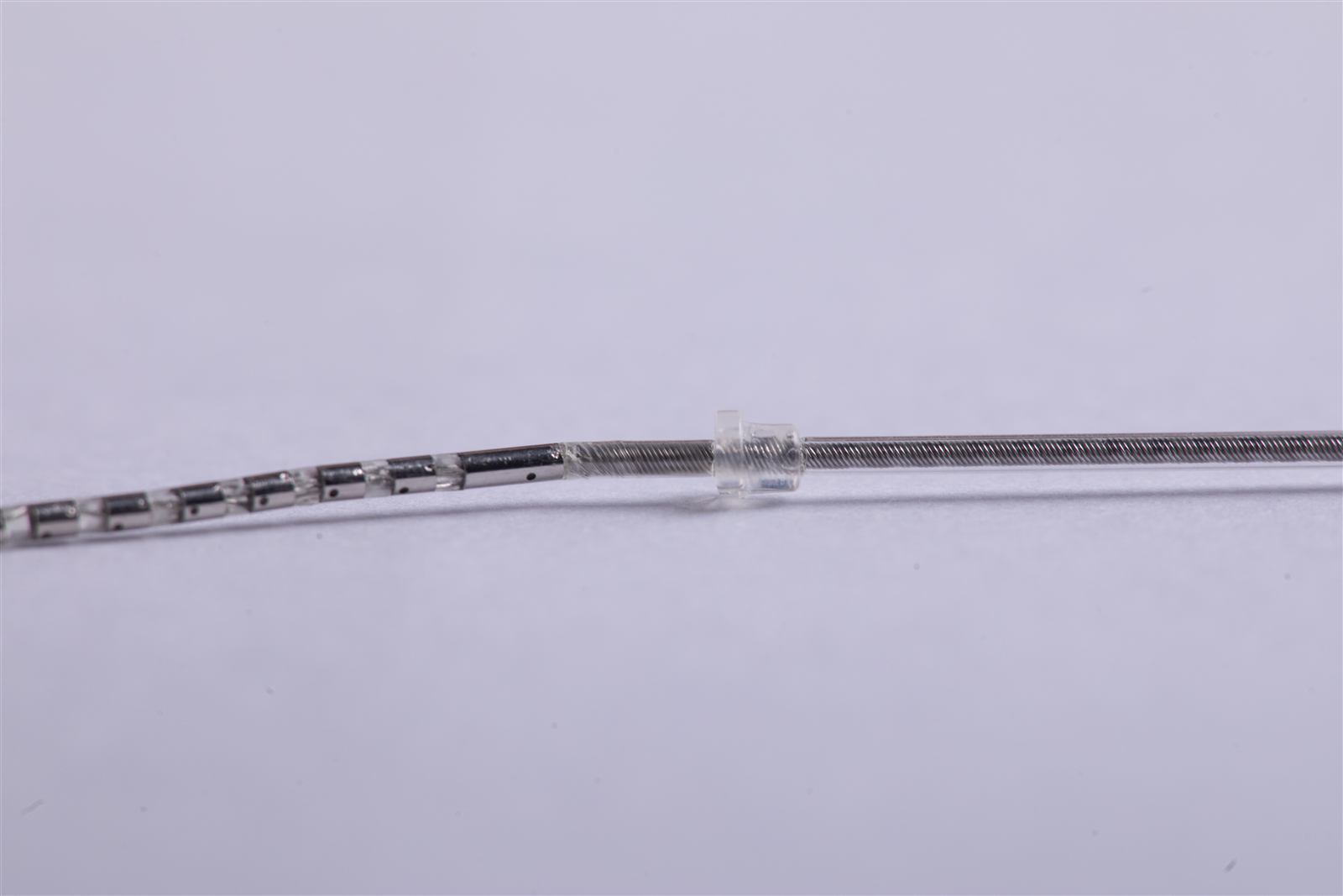
Platinum electrodes and PtIr electrodes
Platinum and platinum-iridium are distinct material specifications. If a drawing says PtIr, provide the nominal alloy composition, including the iridium content and how it is expressed, together with the applicable composition limits or material specification. Give a separate callout for each part in the electrical path. The exposed contact can have a different material from the conductor attached to it. Published device documentation includes an example of platinum contacts joined to PtIr wires in an electrode array. See the FDA summary describing the contact and wire materials.
State the required material condition if the part will be formed, bent, welded or crimped during assembly. Wire in a specified condition and a formed contact of the same alloy can respond differently to assembly steps. If a surface is coated, distinguish the base material from the coating and identify where the coating starts and stops. A solid PtIr contact and a contact with a deposited PtIr layer have different specifications for composition, surface and inspection. See research on electrodeposited PtIr coatings.
Electrode contacts by geometry and function
| Component | Role and details to define |
|---|---|
| Ring electrode | Contact around a catheter shaft or cylindrical carrier. Define the diameters, axial length, edge profile, contact location and attachment area. |
| Disc or shaped contact | Contact with a localized exposed face. Specify face size, thickness, edge profile, seating depth and exposed area after assembly. |
| Fine wire or wire-form contact | Conductor to a contact, formed terminal or exposed sensing tip where specified. Define alloy, condition, diameter, profile, insulation and end condition. |
| Electrode lead subassembly | Contact joined to a conductor. Define contact layout, routing, joining area, lead length, channel mapping and inspection points. |
| Radiopaque marker band | Imaging reference on a shaft or assembly. Include dimensions, mounting position and radiopacity requirements for the designated test setup. |
Begin with platinum-iridium electrode rings for cylindrical contact drawings. For a disc or another shaped contact, review platinum-iridium precision components. When the requested part includes the conductor and its termination, see finished electrode leads. If your team forms or joins the contacts, see platinum-iridium fine wire for the conductor specification.
Catheter electrodes, neural contacts and markers
A drawing for catheter electrodes should show each contact relative to the shaft tip or another assembly datum. On a multi-contact design, specify spacing, the exposed length of each ring and its channel assignment. Include the finished shaft diameter across the ring and its neighboring polymer. A smooth transition depends on both parts and the assembly process. If there is a window for joining a conductor to the ring, identify its position around the shaft and its relationship to nearby features. Medtronic’s published mapping catheter specifications give one example of PtIr electrodes.
Neural sensing contacts and stimulating electrode components can use individually addressed contacts on the same lead. Their drawings should identify which channel connects to each position and which face or segment remains exposed. For a wire-form microelectrode, specify the exposed tip dimensions and where the surrounding insulation ends. For a patterned microelectrode, specify the opening in the insulation and its position relative to the conductive site. Published studies on platinum microelectrodes show that geometric scaling affects impedance. Use the test configuration and acceptance limits defined for the design when comparing candidates. See the FDA summary describing a sensing and stimulation lead and research on platinum microelectrode impedance.
A radiopaque band can share the alloy and appearance of a ring electrode. Its design function is to create an imaging reference. An electrode contact’s function is electrical, so its drawing establishes the exposed conducting surface and connection to a channel. If a component serves both roles, specify the electrical and imaging requirements separately. An assembled lead adds conductors, insulation and terminations. The device design and validation plan define the remaining elements of a finished device. See ASTM F640 radiopacity test methods.
Define the exposed surface and assembly fit
Define the exposed geometric area using the dimensions of the contact surface that meets the measurement medium after assembly. Adhesive, overmold or insulation can cover part of a contact. Dimension those boundaries on an assembly drawing so the intended area can be inspected. A ring with a partly covered circumference or a disc with material extending across its perimeter can have a smaller exposed area than its raw dimensions suggest. Where a defined finish matters, specify the surface region and roughness or visual criteria. For small contacts, establish how to locate and measure the exposed boundary.
Set dimensions from the features that control fit. For example, define the ring bore relative to the shaft and the outer contact surface relative to the finished device profile. Include relevant form tolerances when the ring can become oval or the disc can rock in its seat. Call out burr limits and edge breaks at the interface with a sleeve or conductor insulation. If the stack includes multiple rings, show how accumulated axial tolerances affect spacing between the first and last contact. Identify the datum scheme and tolerancing standard, if one applies. See ASME Y14.5 dimensioning and tolerancing.
When qualifying a fit, agree on the condition of the part during inspection. A thin ring may read differently when free, supported in a fixture or mounted on the shaft. Specify which state controls acceptance, particularly if the measurement method can deform the part. Identify which features need an inspection result for every part, which can be verified by sample and which are evaluated at the subassembly stage.
For example, a short ring may have one edge that sits against an assembly stop and one edge that meets a polymer transition. Label those edges, locate the near edge relative to the datum and specify the allowed step at the finished transition. Include a section view when the bore has relief or the wall changes near the connection. The view helps distinguish dimensions checked on the loose ring from those checked after assembly.
Electrical checks and incoming inspection
A continuity or end-to-end resistance check confirms the conductive path between defined test points. Electrode interface impedance describes a different behavior and depends on exposed geometry, surface and test conditions. If interface impedance belongs in the acceptance plan, state the measurement frequency or range, test medium, electrode setup and stage of assembly. Keep this requirement separate from the resistance limit for the wire and joint. See an FDA example of connector-to-contact testing.
For a joined lead, call out the position and profile of the joint, the conductor orientation and the points for any mechanical test. A pull test needs an agreed loading direction and fixture because different setups load the contact and conductor differently. Identify cosmetic and functional surfaces on the drawing, along with damage or residue limits. For an insulation boundary, specify where to inspect it and how to identify any regions where coverage is intentionally interrupted.
List the evidence required at receipt, such as a material report, drawing revision, lot identification, dimensional results or assembly test records. For a first article, agree how to measure small bores, short exposed lengths and surface defects. See the MOOSEN quality page for additional context. If several visually similar electrodes are used in one build, state how parts and lots remain identifiable through unpacking and assembly. A labeled package or tray map can preserve the link between the part number and its report.
If an exposed electrode area is specified, identify the exact assembly stage at which it will be measured. An overmolded ring and an unassembled ring can have the same bore and outside diameter while presenting different exposed lengths. Dimensional inspection and electrical acceptance should refer to the same state. A marked assembly section can show which portions of the surface are expected to remain open after the conductor, sleeve and insulation are in place.
Compare prototypes with a tracked configuration. Record the drawing revision, material and contact location for each build and use the same connection, mounting and inspection setup for a like-for-like comparison. If the device program calls for multiple positions with the same part shape, include a map identifying the channel and end location. That map also helps quality teams tie receiving records to the intended locations in the lead or catheter assembly.
Request a quote for a custom electrode component
Send the drawing revision, material callout, quantities and delivery form. Identify whether you need loose rings or discs, fine wire, a contact joined to a conductor or an electrode lead with defined terminations. Highlight critical fit dimensions, exposed area and traceability. If joining, coating or insulation happens later, show it on the assembly drawing and indicate who carries out each step. For an early design, include the carrier geometry, contact location and planned prototype acceptance checks.