
MEDICAL FEEDTHROUGH DEVELOPMENT
Hermetic Rectangular Connector
MOOSEN develops drawing-defined conductive parts for rectangular medical feedthrough connectors. Pin pattern, mating geometry and assembly interfaces are engineered against the customer’s housing and ceramic-seal specification. The complete hermetic assembly remains subject to customer qualification.
Titanium housing · Alumina insulation · Custom signal channels
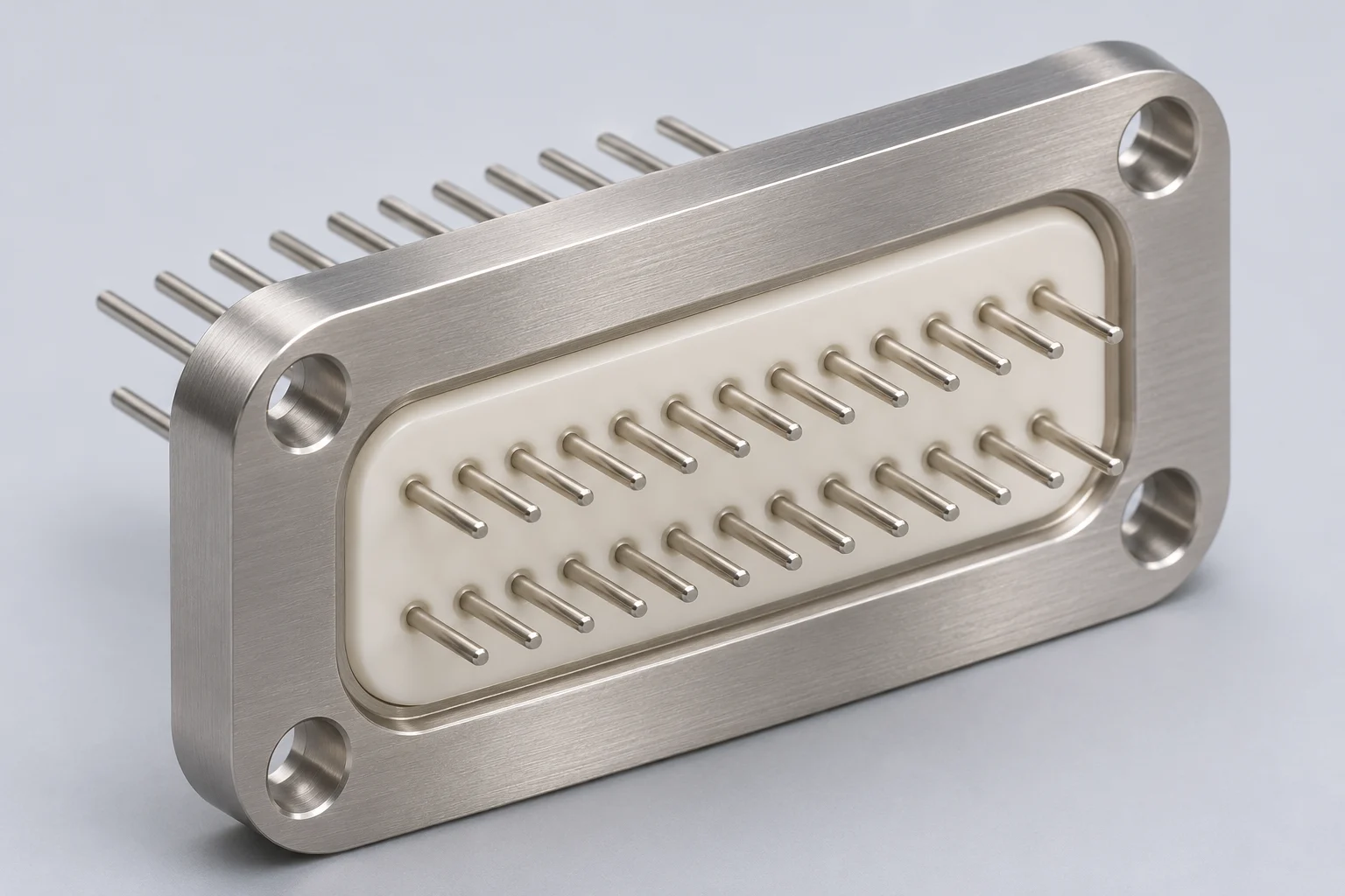
Documented feedthrough platform
MOOSEN catalog features a multi-channel miniature feedthrough
Material integration
Titanium, alumina and Pt–Ir conductors in the published product family
Configurable channels
Pin count and arrangement reviewed for the required interface
Defined acceptance
Seal and electrical checks tied to the approved design
THE COMPONENT ROLE
A sealed electrical path in a compact package
A hermetic rectangular connector combines multiple electrical paths with a package boundary intended to resist gas and moisture ingress. The rectangular outline can help organize contacts along a device housing or bulkhead. The actual seal design depends on the material system, joint geometry and verified manufacturing process.
MOOSEN’s published miniature feedthrough family uses a titanium-alloy shell, alumina ceramic insulation and platinum–iridium signal conductors with precious-metal joining. A rectangular package is a project-specific development direction, with final construction and test criteria established through engineering review.
Sealed material interface
Housing, insulator and conductor materials are considered together at the seal boundary.
Organized pin field
Contact count, pitch and arrangement are developed around signal routing and device space.
Integration-ready envelope
Flange, mounting and termination geometry are reviewed with the mating assembly.
DESIGN ELEMENTS
Hermetic rectangular connector architecture
MOOSEN engineers connector components as a coordinated set of material, pin-pattern and interface decisions. Rectangular geometry is developed to the customer-controlled design and qualified at the complete assembly level by the device maker.
Titanium housing
The cataloged feedthrough uses a titanium-alloy shell. A rectangular flange and attachment features are reviewed against the housing drawing.
Ceramic insulation
Alumina separates signal conductors from the metal housing and forms part of the sealed interface.
Pt–Ir conductors
Fine platinum–iridium conductors are an established option in MOOSEN’s feedthrough family; channel layout is drawing-specific.
Joining interface
Precious-metal joining is documented in the feedthrough family. Joint details depend on the selected material and geometry.
DRAWING-BASED CONFIGURATION
Custom rectangular connector options
These are engineering review areas, not a list of fixed stock specifications. MOOSEN establishes manufacturability and acceptance for each configuration.
| Configuration area | Project approach |
|---|---|
| Package format | Rectangular envelope, flange and mounting details to approved drawing |
| Contact layout | Pin count, row pattern and spacing reviewed for signal paths and assembly access |
| Material stack | Titanium alloy, alumina and Pt–Ir options based on MOOSEN’s published feedthrough family |
| Termination | Pin length, orientation and mating features defined for the customer assembly |
| Hermetic acceptance | Leak method and limit established for the specific design; no universal rating is claimed |
| Electrical checks | Continuity and insulation criteria agreed for the application |
| Release evidence | Visual, dimensional and project-specific inspection records |
MOOSEN EXPERIENCE
From miniature feedthroughs to custom package layouts
MOOSEN’s product catalog documents miniature feedthroughs for implantable electrical connections. It describes multi-channel signal transmission through a titanium, alumina and Pt–Ir material system, with pin number and arrangement available for customization.
For a rectangular connector, this experience guides early decisions about the seal architecture and contact layout. The rectangular form and its hermetic performance are qualified against the customer’s specific design; the concept illustration on this page does not represent an existing production model.
Engineering focus
Material compatibility, conductor routing, joint access, mounting geometry and inspection all need to work as one package.
MANUFACTURING & QUALITY
Production and inspection at MOOSEN
Real production capability matters behind a precision feedthrough design. MOOSEN’s facility supports small-component processing and inspection; project-specific seal and electrical tests are defined before release.


Component preparation
Metal, ceramic and conductor features are prepared around the approved process route.
Interface control
Pin position, joining surfaces and housing features are reviewed as critical interfaces.
Verification
Visual, dimensional, electrical and leak checks are selected for the agreed specification.
Select the right component for your assembly
Compare mounting envelopes and conductor layouts for rectangular interfaces before choosing an assembly route. Check the mating face, panel opening and terminal access before carrying a rectangular layout into a new enclosure. The flange drawing and contact schedule together define the configuration reviewed for a rectangular connector quote.
| Component route | Choose it when | What to confirm |
|---|---|---|
| Hermetic rectangular connectors | multiple contacts in a drawing-defined rectangular sealed interface | Use the approved drawing and assembly method as the decision basis. |
| Hermetic single seal terminals | only one sealed electrical path is required | Review this component |
| Medical hermetic feedthrough components | the package architecture has not been selected | Review this component |
Prepare a useful RFQ
Include the latest flange drawing and identify the mating side, cutout and contact layout for each variant. The contact form accepts a flange drawing, mating-face schedule and the report requirements for prototype and recurring quantities.
- channel layout
- pitch
- envelope
- Pt–Ir conductor interface
- joining and agreed seal testing
Evidence to agree: the shell and insert materials, flange and contact positions, and electrical and leak results specified on the rectangular connector drawing. Panel fit and electrical acceptance depend on the specific connector geometry and assembly conditions.
FREQUENTLY ASKED QUESTIONS
Dimension the flange and enclosure opening together
Use the enclosure drawing to locate the connector, starting with the face where the flange seats. Reference the cutout and mounting pattern to datums that machining and inspection teams can reproduce. Give the opening width and height, corner radii, wall thickness and flange footprint. Include a section through a corner or mounting feature to show how far the shell projects through the wall. Front and rear mounting can require different cutouts, so identify the installation side and the space available for the mating plug.
For a bolted flange, define the hole centers, hole or thread sizes and hardware access. Identify the sealing surface and the separate gasket or sealing feature if the assembly requires one. For a permanently joined flange, show the joint path, mating materials and clearance for joining and inspection. If a board or rigid harness sits behind the wall, locate it from the same seating face. The drawing then provides a common reference for flange fit, rear projection and contact engagement.
Lay out the contact mix and keying
Provide a numbered mating-face drawing and corresponding circuit schedule. List which positions carry power, signals or grounds and give the relevant electrical requirements for each group. If the drawing combines different contact sizes or termination styles, identify each position and the rear space it needs. Mark unused positions and describe how the drawing treats them. For an existing plug, supply its full part number and interface drawing, including engagement depth and locking hardware where applicable.
Show the polarization feature in the same view as the contact layout. A shaped shell can control orientation. Where adjacent connectors use different circuit maps, specify the keying or spacing that prevents the wrong cable from mating. Label the rear view so the wiring layout can be checked against the mating face. See AMETEK rectangular connector examples for the range of design approaches.
Agree on installation and inspection before quoting
Identify dimensions to check on the first parts, such as flange seating, cutout clearance or contact position. If a leak test is required, state the acceptance limit, reporting units and procedure. Specify which checks apply to the connector as delivered and which apply after installation. For instance, list whether the report covers the feedthrough body, the flange-to-wall joint or an assembled enclosure. A written test boundary gives the sourcing team a way to compare proposals for the same scope.
Think through connector installation before releasing the first drawing. If the connector slides in from the interior, identify the handle or tool clearance before a nearby assembly is installed. If rear connections are made first, include the space a wire bundle needs to move while the flange is seated. For serviceable equipment, state the free space required to remove the external mating part without disturbing its neighbors. This can identify practical constraints that do not appear on the part envelope.
Include the drawing revision and the inspection records required with delivery. Define which datum faces the inspector can contact and what projection measurements should accompany the lot. If two connector variants share the same enclosure aperture but use different pin arrangements, identify both variants on the package label or inspection records so the receiving team can distinguish them.
If the enclosure uses a round mating interface, compare installation and service access in the circular and bulkhead connector guide. For a single-conductor penetration, see hermetic single-seal terminals. Share the flange drawing, circuit schedule and inspection requirements when you request a rectangular connector review.
Hermetic rectangular connector FAQs
Does MOOSEN offer a standard rectangular connector model?
MOOSEN’s published catalog documents miniature feedthroughs and configurable pin arrangements. Rectangular configurations are developed against a customer drawing rather than presented here as a verified stock model.
Which materials are used in MOOSEN feedthroughs?
The published feedthrough family specifies a titanium-alloy housing, alumina ceramic insulator and platinum–iridium signal conductors. Material selection for a rectangular design is confirmed during engineering review.
Can the pin arrangement be customized?
MOOSEN’s catalog identifies pin count and arrangement as customizable. The final pattern, spacing and termination are determined for the device interface.
How is hermeticity specified?
The test method, acceptance limit and inspection scope are defined for the approved assembly. This page does not assign a universal leak rating to every rectangular design.
Is this a finished implantable medical device?
No. MOOSEN supplies components for integration into customer-controlled devices. Finished-device validation and regulatory decisions remain with the device manufacturer.
Can a custom pin map and connector outline be quoted?
MOOSEN uses the customer’s pin arrangement, pitch and housing drawing to quote the component geometry and agreed inspection scope.
Can prototype parts support our package validation?
MOOSEN can supply agreed samples for fit and joining trials, with production released against the approved drawing and acceptance criteria.
CONNECT WITH MOOSEN
Develop a sealed connector interface
Talk with MOOSEN about the package outline, signal paths, material stack and inspection strategy for your rectangular feedthrough program.