
MOOSEN / PRODUCT SYSTEM
Finished Electrode Leads
MOOSEN manufactures customer-designed finished electrode leads as well as their contacts and conductors. Product forms include paddle, cylindrical, directional, sensing, cuff, membrane, flexible and extension leads.
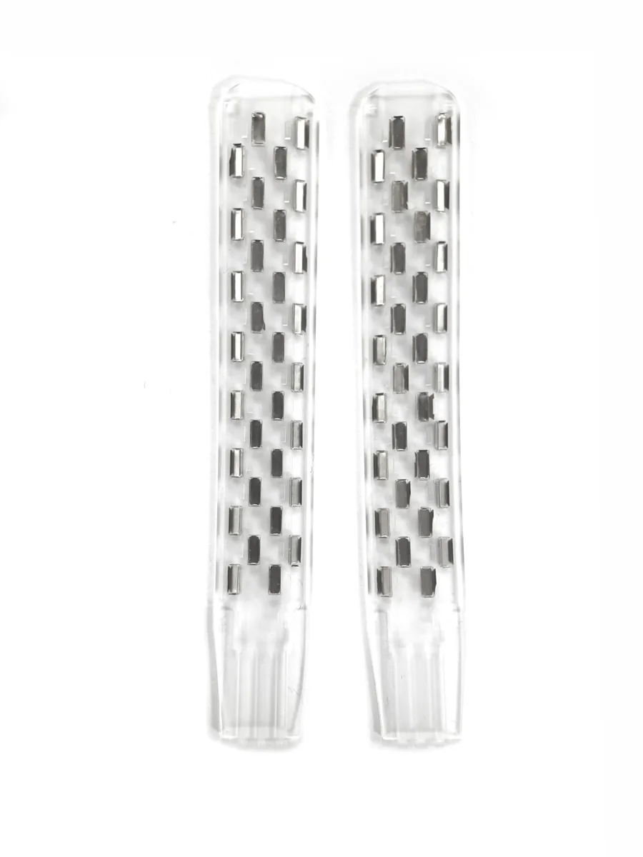
THE CATEGORY
Built around the device specification
Lead architecture determines the contact pattern, lead body, flexibility, conductor route and termination. MOOSEN can provide the specified finished lead or component scope; the customer defines the device requirements and remains responsible for final device qualification.
PRODUCTS IN THIS SYSTEM
Explore every product pathway
Paddle, Cylindrical and Directional Electrode Leads
Finished lead options and parts for three electrode geometries.
Flexible, Cuff and Membrane Electrode Leads
Finished lead options and interfaces for conformable designs.
Platinum Iridium Electrode Rings
Pt–Ir contact rings for exposed electrical interfaces.
Sensing and Diagnostic Electrode Leads
Finished lead options for signal collection pathways.
Electrode Extension Leads
Customer-designed extension lead assemblies and components.
WHY MOOSEN
From drawing to controlled component
Contact, conductor and insulation interfaces reviewed as a system
Multiple lead geometries supported through drawing-defined parts
Prototype and inspection scope matched to the intended assembly
SPECIFICATION INPUTS
What to include in your RFQ
Lead and contact geometry
Exposed contact and conductor interface
Insulation and termination
Continuity, dimensions and release records
LEAD INTEGRATION
A typical component brief
A device manufacturer specifies a new electrode lead geometry. The drawing identifies the lead body, exposed contacts, routing, termination, insulation transitions and inspection criteria. MOOSEN can quote a finished lead assembly or the agreed component scope for the customer’s qualification program.
INCOMING INSPECTION
What procurement teams can verify
Buyers can assess interface fit, conductor continuity, contact finish and the inspection records agreed for the order.
Request records that identify the lead revision, contact positions and agreed checks for the delivered assembly.
Decide whether the order is for a complete lead or an individual part
An electrode lead can combine contacts, conductors, insulation and one or more terminations in a single customer-defined delivery. A contact or fine wire can also be quoted separately if your team forms or joins the lead in-house. Identify the intended item on the drawing and specify who performs the downstream assembly operations. The difference affects the dimensions and electrical checks that can be completed before delivery.
For a complete lead, show the positions of the electrodes, their channel assignments, conductor route and the connector or free-lead end. Call out the features that establish orientation when the part is first placed into a fixture or device. If the order covers a subassembly, define which items it already includes and which are added by the OEM. Tie the inspection document to that delivered state so its results are read against the intended configuration.
For components supplied loose, specify the part’s approved alloy, dimensions, finish and any geometry needed for joining. The lot record can then describe that part’s actual acceptance. A separate finished-lead test should verify the electrical connection, insulation and location of contacts after assembly where those checks are part of the project.
Compare lead formats by contact arrangement and interface
A paddle lead uses a carrier with a defined arrangement of contacts. The drawing should show the orientation of that carrier, the reference from which contact position is measured and how the conductor bundle exits. Cylindrical and directional lead designs use a different surface arrangement. For a cylindrical form, give the profile, length and contact position along the carrier. For a directional form, identify the angular reference and the channels assigned to each sector. Review paddle, cylindrical and directional electrode leads to compare those interfaces.
Flexible and cuff formats can have a contact layout that needs to be specified in both free and installed conditions. Indicate the expected curvature or carrier geometry where it controls contact position, exposure or routing. Provide a reference for closure or retention features and show the lead exit relative to the carrier. The flexible, cuff and membrane electrode lead page describes related formats for drawing-based review.
For a sensing lead, identify the exposed contact arrangement and which channels will be measured. Define electrical test points and the relevant connector or measurement interface. For an extension lead, define the mating geometry at both ends and keep each conductor path in the pinout. See the sensing and diagnostic lead overview and customer-designed extension leads.
Specify the contact, conductor and insulation as separate features
Use a material callout for each part of the electrical path. A ring contact, the wire attached to it and the equipment-side terminal can have different materials. Where the contact is platinum-iridium, supply the required alloy designation and define the exposed surface on the assembled drawing. For a cylindrical contact, show the finished profile through the ring and nearby insulation. See electrode ring drawings and interface requirements for that component form.
Show the route of the conductor through the lead and the section available for joining or exiting the carrier. If the lead includes a specified sleeve, coating or jacket, mark its coverage and the locations where metal must remain accessible. A completed outside diameter can include several layers. Add the limits that matter to the actual mating feature, as well as how the part is held during measurement.
For a design with several electrodes, carry the contact names or numbers across the assembly drawing, circuit map and receiving document. Specify the view from which each position is numbered. In a lead with an angular reference, mark that reference on the connector or part drawing. Consistent identifiers help the supplier document the correct relationship between contact position and electrical path.
Check the delivered lead before choosing a production requirement
Define functional checks at clear points in the build. For a complete lead, a continuity check can identify the path from a connector position to the corresponding contact. Specify electrical separation where two paths must remain isolated. For incoming loose rings or conductors, specify geometry and material documentation relevant to those items. If the project calls for a test at the exposed electrode interface, state the conditions and how the assembled lead is prepared for the test.
Agree what a sample must show before the assembly is released. A first trial may check physical fit and handling, while another determines whether the intended termination and contact mapping are correct. Include the equipment or fixture drawing needed to simulate the relevant interface. Where the test depends on lead placement, state the element that locates the part and which motion or bend state applies.
For recurring orders, specify the inspection records needed for the agreed build state. Document the drawing revision, material designations and electrical or dimensional results required for incoming review. Identify any lot separation or labeling used to distinguish several lead versions. A delivery of different contact counts, lengths or connector variants should give the receiving team a reliable way to identify each assembly.
Identify external electrode cables by their mating parts
Some equipment leads use external connectors and replaceable electrode accessories. If a project calls for this style, provide the machine-side and electrode-side part references separately. The 3.5 mm to 2 mm pin lead wire page explains the drawings needed for that particular interface. For a general terminated cable or conductor assembly, compare the requirements on the medical wire assembly page.
Even when two programs use the term electrode lead, the ordered item may differ in connector layout, exposed contact length, insulation and verification. Give the exact drawing and counterpart references for the program. If you are replacing a cable with an established design, include the dimensions and wiring schedule that have to match. If a prototype will use a revised mating part, identify that dependency on both drawings.
Prepare a request for an electrode lead review
Send the current assembly drawing and component list, with the contact configuration, wire construction and material callouts. State which operations are included in the requested delivery and show any part you will supply. Include expected prototype and production quantities separately, and indicate what data will support review of the sample and release of recurring quantities.
If the design has unresolved choices, list the ones that affect physical fit, conductor routing and electrical checks. Identify which surfaces or terminations need proof of concept before the drawing is finalized. For repeat deliveries, state how the part and lot should be identified. MOOSEN can review the supplied configuration, assembly boundary and required supporting records for the project.
For a lead family that includes several contact counts, prepare a controlled table of lengths, connector references and electrical paths for each version. A production lot can then be inspected against the variant that was ordered. Where a model changes only the carrier or the distal contact arrangement, include a reference that makes the difference visible even after packaging. Label any prototype that uses a provisional connector so it is evaluated against the correct device assembly. This is particularly useful when a program sends multiple drawing revisions to a supplier during development.
NEXT STEP
Send your specification to MOOSEN
Share the drawing, intended application, target quantity and required inspection or documentation. Our team will respond with the component scope and technical questions needed for quotation.