
MOOSEN BLOG
Marker Band Dimensions and Tolerances: How ID, OD, and Wall Thickness Affect Fit
When we review a catheter marker band drawing at MOOSEN, we ask where the band sits, how it gets there, and what outside profile the finished catheter must meet. Those answers tell us which dimensions deserve the closest attention. A band can look like a good fit on a drawing and still bind on the largest shaft that the drawing allows.
Use the smallest permitted marker band ID and the largest permitted shaft OD to check minimum diametral clearance. Then assess the finished catheter profile and any local minimum wall requirement separately.
The example below follows a closed tubular band intended to slide over a round shaft before attachment. The arithmetic is a first drawing check. The assembly method and acceptance criteria still need to be agreed for the project.
What do ID, OD, wall thickness, and length mean?
| Dimension | What it controls |
|---|---|
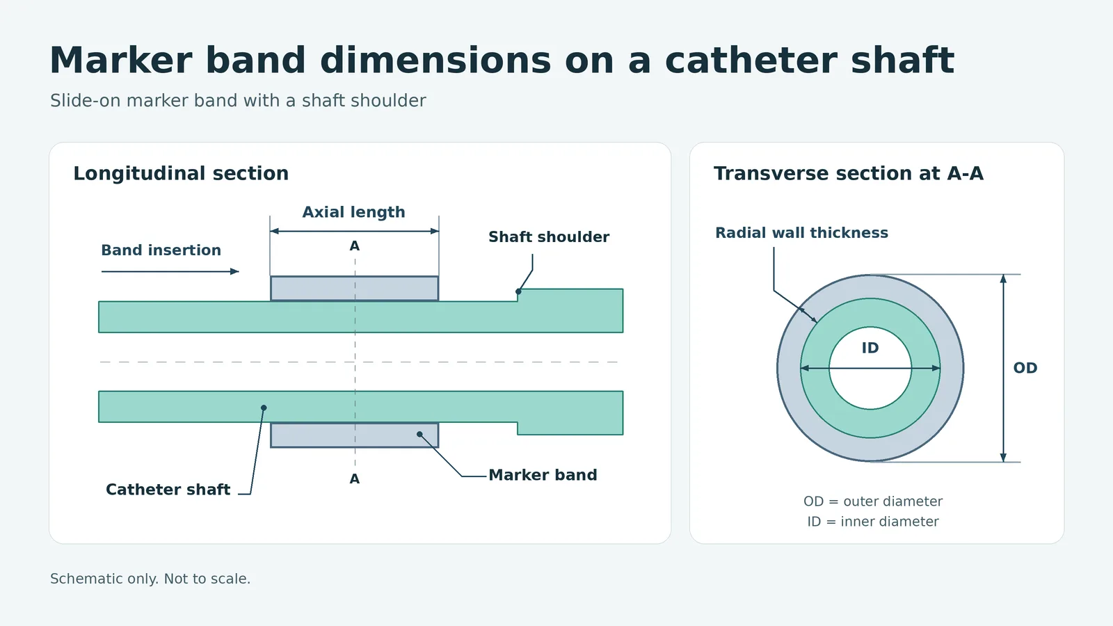
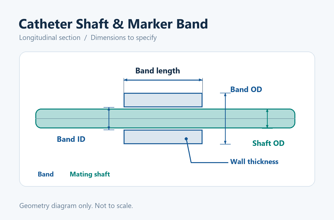
| ID (inside diameter) | The size of the bore that passes over the catheter shaft. Compare it with the shaft OD along the full insertion path. |
| OD (outside diameter) | The outside size of the band itself. Check the finished catheter OD at the marker as a separate assembly dimension. |
| Wall thickness | The radial thickness of the metal between the bore and outside surface. Note whether the drawing calls for a nominal value or a local minimum. |
| Axial length | The face-to-face length along the shaft. Check the available seat length and how each end lines up with adjoining features. |
Check the shaft diameter that the bore must pass during installation. A shoulder or transition along that route can be larger than the final seat. On the assembly drawing, show the insertion direction and identify the largest feature the band must clear.
How do you calculate nominal wall thickness?
For a concentric band with a 0.90 mm OD and a 0.80 mm ID, the nominal radial wall is 0.05 mm. The difference between the diameters includes material on both sides, so divide it by two to get the thickness on one side.
If the bore is offset, one side can be thinner than the other even when the ID and OD are within their limits. If the thinnest point matters, specify minimum local wall thickness and agree where and how to check it. For a tight radial space budget, see our thin-wall platinum-iridium marker bands.
Can a band fit at nominal size and still interfere at the tolerance limits?
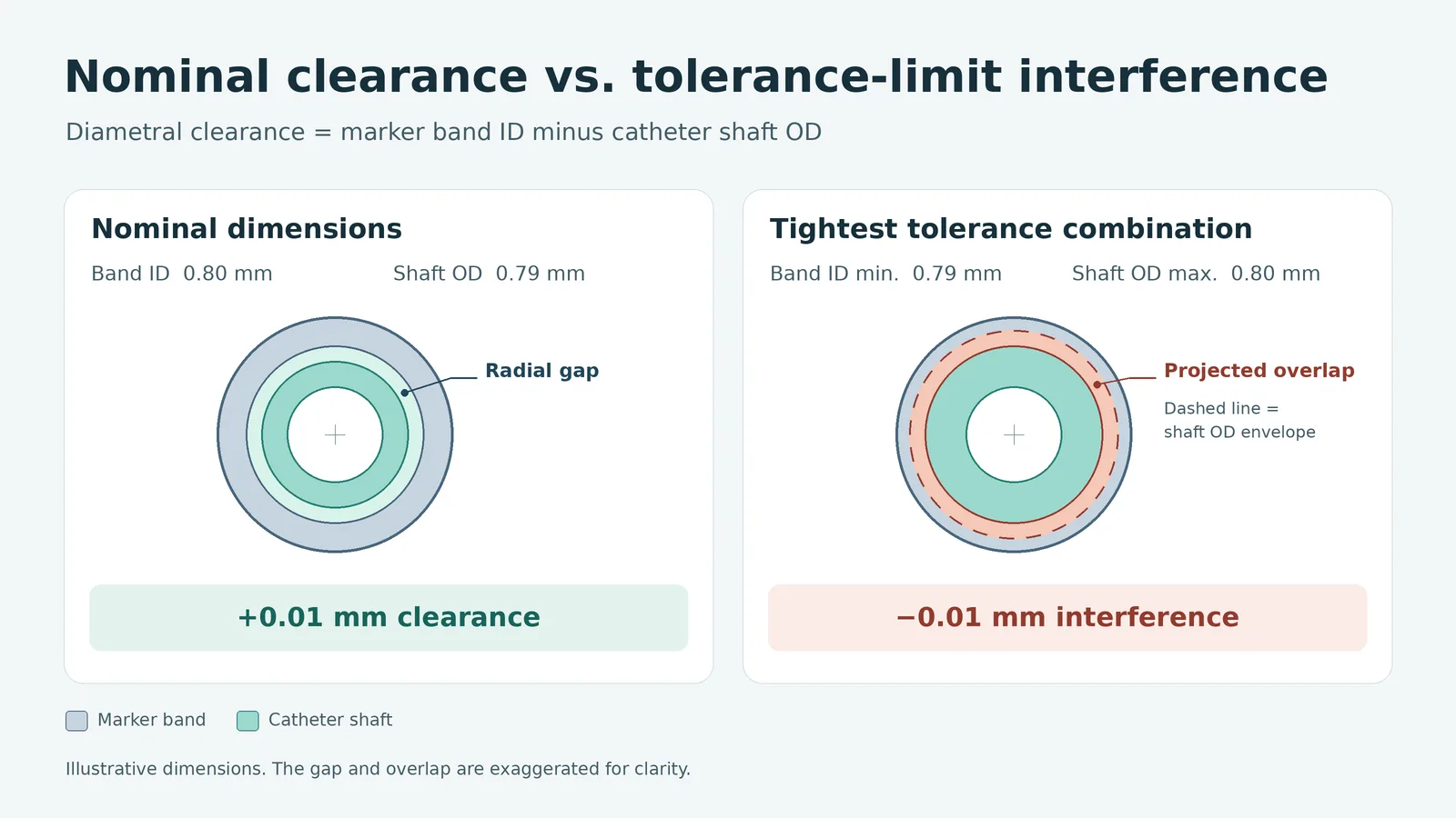
Yes. Suppose a band has an ID of 0.80 ± 0.01 mm and the shaft has an OD of 0.79 ± 0.01 mm. Both parts can meet their drawings while one combination interferes. These figures are illustrative and do not represent MOOSEN production tolerances.
| Fit scenario | Band ID minus shaft OD | Result |
|---|---|---|
| Nominal dimensions | 0.80 − 0.79 mm | +0.01 mm clearance |
| Tightest combination | 0.79 − 0.80 mm | −0.01 mm interference |
| Loosest combination | 0.81 − 0.78 mm | +0.03 mm clearance |
The negative result means possible interference in this slide-on example. If the design calls for a press fit, review it against the intended interference and assembly process. For a slide-on fit, compare the minimum clearance with the margin the process requires. Check the actual parts for shape and edge condition if they bind during a trial.
Which dimensions should control acceptance on the drawing?
Start with the function the part has to meet. ID often drives shaft fit. OD or the installed envelope can drive clearance to the next component. A minimum local wall can become a separate acceptance requirement. If you show ID, OD, and wall together, state which values control acceptance and which are references. Review the combined limits if all three must be controlled.
| Requirement | Callout to review | Inspection question |
|---|---|---|
| Slide onto the shaft | Band ID limits and mating shaft OD limits | Where is the largest shaft diameter the band must pass? |
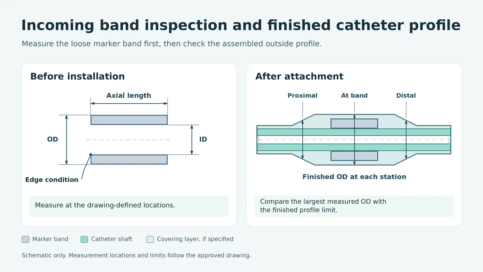
| Meet the finished profile | Band OD and maximum assembled OD where applicable | At which axial locations should the finished assembly be measured? |
| Maintain metal thickness | Minimum local wall when critical | Where and by what method should the minimum be evaluated? |
Also show what happens after installation. Where a recess, covering layer, or attachment step affects the final profile, define the limit on the assembled catheter and state where to check it. A finished profile callout belongs on the assembly drawing. See our custom catheter marker band page for more on shaft and drawing interfaces.
What should you verify before releasing the drawing?
- Before installation. Check band ID, OD, axial length, and drawing-defined edge condition. Where the edge has a chamfer or radius, agree where the diameter reading should be taken. If minimum wall or ovality governs acceptance, record the agreed method and measurement location.
- During a representative assembly trial. Confirm that the band can travel to its seat and stay in the intended axial location after attachment. Where feasible, include parts near the fit limits. Review retention if the design specifies it.
- After installation. Measure maximum OD at the marker and adjoining transitions in the relevant finished condition. If the application has an imaging requirement, check visibility on the representative assembly against the device team’s criteria.
We ask for the band drawing revision, the shaft OD range along the insertion path, and a section through the installed band. Add the maximum finished OD, attachment method, and any inspection records your receiving team needs. For material and order details, use our marker band specification guide.
What else should you check when specifying marker band dimensions?
Is diametral clearance the same as the gap on one side?
Diametral clearance is the difference between the bore and shaft diameters. In an ideal centered fit, a diametral clearance of 0.01 mm gives a radial gap of 0.005 mm per side. An off-center shaft can reduce the gap on one side.
Why can a band bind even when its measured ID is in tolerance?
Check the tightest section of the bore, the entry edge, and the actual shaft along the insertion path. A diameter reading taken at one location may miss a smaller opening elsewhere. Compare parts using the locations and methods agreed on the drawing.
Which section should I include with a drawing review?
Show the band in place with the shaft, any recess, and any covering layer. Include the band location and the points where the finished profile limit applies. This lets us review where the band sits and how the overall diameter will be checked.
Which MOOSEN marker bands are relevant to your drawing?
Platinum-Iridium Marker Bands
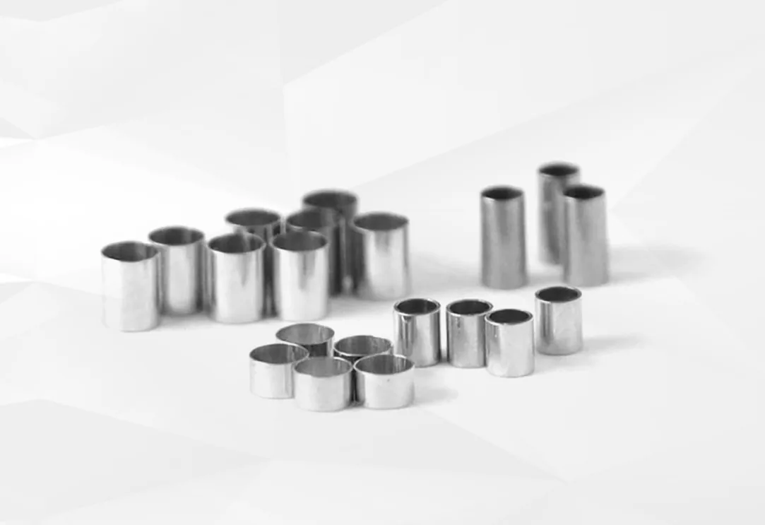
Standard and drawing-based radiopaque bands for catheter and delivery-system applications.
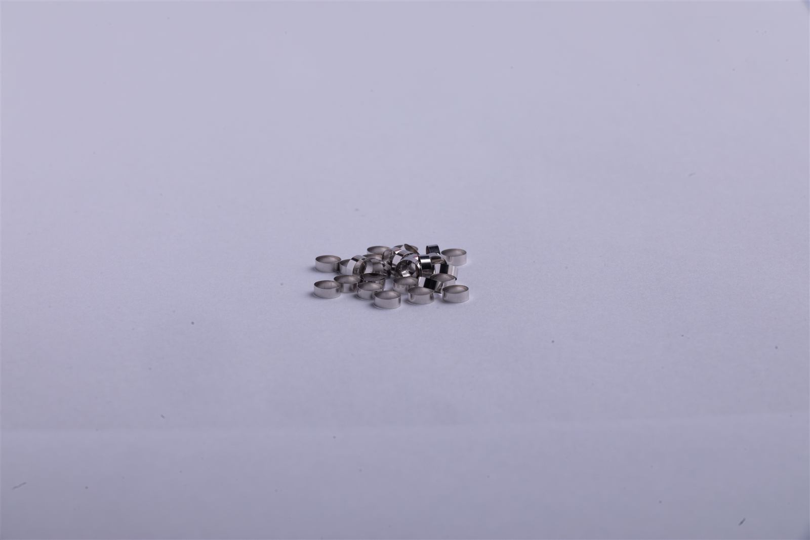
Thin-Wall Platinum-Iridium Marker Bands
A configuration to review when the available radial space is limited.
Custom Catheter Marker Bands
Drawing-based options for a defined shaft interface and installed profile.
Have a shaft drawing or a tight fit to review?
Send your band dimensions, shaft diameter range, and maximum installed profile. Mark the features that control acceptance so we can discuss the drawing and the checks needed for a sample.