
Radiopaque Markers for Medical Devices
MOOSEN supplies platinum-iridium radiopaque markers for medical device assemblies. Compare bands, rings and discs by mounting location and fit, then send your drawing for review.
Upload Your Drawing Compare Marker Types
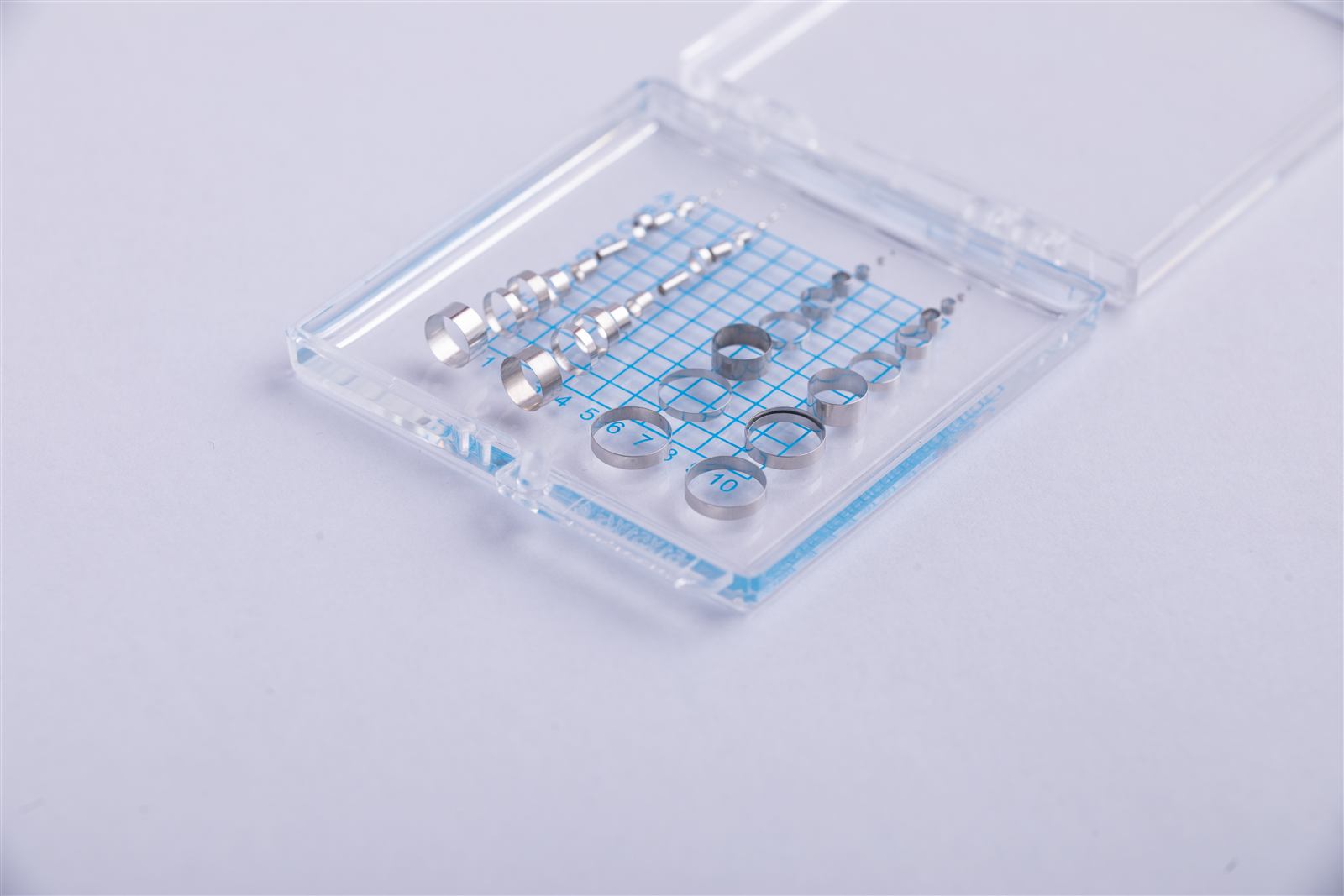
What Does a Radiopaque Marker Show?
A radiopaque marker makes a defined location on a medical device visible under X-ray or fluoroscopy. A marker band can identify a location near a catheter tip. On some balloon catheters, two bands mark the ends of the balloon.
Start by identifying the feature that needs to be visible. Then check the available space, the shape of the mating part and how the marker will be attached.
Compare Platinum-Iridium Radiopaque Markers
Platinum-Iridium Marker Bands
Use a short tubular marker when it needs to fit around a catheter shaft or delivery component.
Drawing inputs Shaft diameter, band ID and OD or wall thickness, and axial length.
Platinum-Iridium Marker Rings
Choose a ring when the assembly drawing defines the mating dimensions or an opening such as a slot or C-shaped cutout.
Drawing inputs ID, OD, axial width and any opening or slot dimensions.
Platinum-Iridium Marker Discs
Consider a flat, circular marker for a recess or flat mounting surface.
Drawing inputs Disc diameter, thickness and mating surface dimensions.
Platinum-Iridium Perforated Rings
Choose a perforated ring when the assembly calls for holes in specified positions.
Drawing inputs Ring dimensions, hole diameter and hole location.
If shaft fit, attachment or the finished catheter profile drives your design, see custom catheter marker bands.
Drawing and Inspection Requirements
Show the marker and the part it mates with. For a shaft-mounted band, include the shaft diameter at the mounting location and any limit on the finished outside diameter. For a disc, show the recess or mounting surface.
Include the specified alloy, critical tolerances, edge or surface requirements and the intended attachment method. State the expected sample or production quantity.
Agree on Inspection Before Sampling
Identify the dimensions and edge conditions that need acceptance checks. List any material records or dimensional reports required with the order. If visibility is a qualification criterion, include the imaging conditions and acceptance criteria your team will use to evaluate the assembled device. See MOOSEN quality and inspection.
Start With the Location the Image Needs to Identify
A radiopaque marker is a component designed to create a reference that can be distinguished under X-ray imaging. Define the part of the device that the reference needs to identify. It may be a distal tip, the limits of a working segment or a specific location on a delivery assembly. The marker drawing should show where the component sits in relation to that reference on the finished device.
Decide whether the imaging task needs one marked location or a recognizable relationship between locations. A single element can provide a local reference. Multiple markers may identify the boundaries of a section or two different features, depending on the design. If your drawing calls for two markers, dimension the placement and identify each part number. Include the views and assembled geometry that will be used during evaluation.
Also specify who interprets the marker reference and which views are relevant to that interpretation. A feature visible from one angle can overlap another part when the device is viewed from a different direction. Document the marker location using a stable reference on the device, along with any orientation that affects whether the marker can be seen. This is particularly important when similar markers have different functions or when an adjacent component casts a denser image. Clear references let the design team compare alternative formats using the same imaging task and help purchasing identify which part belongs at each assembly position. A drawing-based request can then separate improvements to marker geometry from changes to the imaging evaluation itself.
Share the space actually available to the marker. The permitted diameter, thickness and length may be set by the surrounding shaft, a covering layer or a recess. A design can have room for more material in one direction than another. That information is more useful during early component review than an undimensioned note requesting high visibility.
Compare a Band, a Ring, a Tube and a Disc
A closed band provides a circumferential form when a shaft can accept a sleeve. The drawing commonly controls the bore, outside diameter, axial length and edge condition. Review the platinum-iridium marker band page if your intended geometry is a short closed marker fitted over a catheter or delivery-system shaft. Show the diameter of the shaft exactly where the marker sits.
An open or slotted ring can be considered when installation access or an adjacent feature changes the assembly sequence. Make clear which part of the ring is open and how the opening is oriented relative to the finished assembly. Compare the platinum-iridium marker ring formats when the assembly needs a different entry path or a particular circumferential feature.
A cut marker tube provides a hollow form when axial length and the usable bore both matter. Identify the surface that remains open from end to end and specify any difference between the ends. See marker tube drawing considerations if the length or bore is the main design constraint.
A disc is a flat format that may suit a seat or location defined by a planar interface. Call out thickness, profile and retention or joining requirements. Review platinum-iridium marker discs where the drawing needs a flat form. In each case, evaluate the form together with the space, mounting arrangement and imaging objective.
Review the Marker in the Intended Imaging Configuration
Platinum-iridium is used in marker designs because it attenuates X-rays. The contrast visible in a specific image also depends on the amount and distribution of material, nearby structures and imaging conditions. A smaller marker may be suitable for one reference location and difficult to distinguish at another. Use the device team’s evaluation plan to establish which configurations are acceptable.
Keep geometry and imaging acceptance linked in the development record. For each prototype, label the marker material, dimensions, location and related drawing revision. Where a marker is covered by a sleeve or placed near another dense component, use a sample that represents that build when assessing the reference. A comparison conducted before final assembly can answer a component question. A separate device-level check addresses how the marker appears in its actual surroundings.
If the prototype study compares two marker forms, decide which feature needs to remain visible and use an equivalent reference for each configuration. Document which dimensions were adjusted and whether the assembly surface changed. Where the imaging task needs to distinguish adjacent references, record their intended spacing as well as the dimensions of each individual marker. This information helps interpret whether the observed result reflects shape, material or location.
Specify the Interface That Holds the Marker
The marker can share a close fit with the shaft or seat in a feature defined by another part. Show a section through the installed position. Identify where the component needs to be located and whether a surface of the marker touches an adjacent part. If the assembly has a strict external profile, annotate the envelope at the marker location rather than using the nominal outside diameter of an unrelated shaft section.
For a band or tube that slides over a shaft, include any dimensional steps that the marker encounters during installation. The diameter at the final position can differ from the largest feature it must pass. If a hole or slot must align with an assembly feature, dimension the pattern relative to a locating surface. The perforated marker band page explains the positional information relevant to a hole pattern.
Define the edge conditions where they affect installation or adjacent parts. The inside edge that first contacts a shaft may have a different requirement from an end face that seats against a shoulder. Include these differences as drawing notes and describe the inspection approach where the requirements govern acceptance.
Combine Sourcing, Inspection and Prototype Planning
Send the current drawing, part quantity and assembly notes together. Clearly distinguish a request to check a standard part from a drawing-based prototype. List the dimensions and the fit or imaging decisions the initial sample is meant to support. For a design that is not ready to freeze, identify the fixed constraints and flag the dimensions that remain open for review.
Confirm what records the receiving team needs for a trial or production lot. These may include material identification, agreed dimensions, visual criteria or packaging identifiers. Give the supplier the material designation and any requirements for lot separation. When several small marker parts are ordered together, request practical labels that tie each package to the agreed drawing and item number.
For an application with a defined shaft and attachment method, use the custom catheter marker design information to prepare the mating-interface details. For an early comparison of different forms, provide a dimensioned sketch that explains the marker function, the available envelope and the device reference it is meant to identify. MOOSEN can review the proposed form and identify the geometry and documentation needed for a quote.
Frequently Asked Questions
Which platinum-iridium alloy should I specify?
Include the alloy grade if your drawing calls one out. If the grade is open, share the marker geometry and imaging visibility requirements so material options can be discussed during review.
Can I check standard marker ring sizes?
Send the target ID, OD or wall thickness, axial width and quantity. MOOSEN can check for a matching standard size and confirm current availability.
Can I request a review before the drawing is final?
Send a dimensioned sketch with the mounting location, available space and dimensions you know. Mark any dimensions or tolerances that are still open.
Request a Radiopaque Marker Review
Send your drawing or dimensioned sketch with the mounting location, estimated quantity and any documentation needed for the quote.