
MOOSEN / PRODUCT SYSTEM
Implantable Connection Components
MOOSEN manufactures implantable contact modules and miniature hermetic feedthrough assemblies to customer-defined designs. Materials, mating geometry, sealing architecture and test requirements are specified for each product.
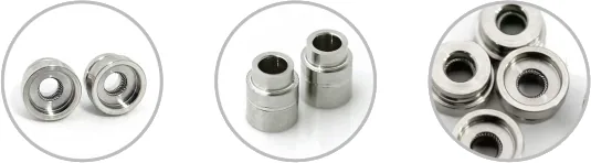
THE CATEGORY
Built around the device specification
Contact modules and feedthrough assemblies solve different interface problems. MOOSEN can supply the specified module or sealed assembly, with component and assembly checks defined by the order. The device maker remains responsible for final system qualification.
PRODUCTS IN THIS SYSTEM
Explore every product pathway
Implantable Contact Modules
Customer-defined contact modules with material and mating features.
Medical Hermetic Feedthrough Assemblies
Miniature sealed feedthrough assemblies with specified housing, ceramic and conductors.
WHY MOOSEN
From drawing to controlled component
Contact geometry reviewed with its mating interface
Conductor and joining features considered before samples
Component inspection and documentation aligned with the customer specification
SPECIFICATION INPUTS
What to include in your RFQ
Mating interface and contact geometry
Material and conductor connection
Joining and insulation boundary
Dimensional and visual verification
DEVICE INTEGRATION
A typical component brief
An active-device team is defining a compact electrical interface. Its package specifies contact geometry, mating component, joining process, seal boundary and incoming inspection. MOOSEN can supply the specified contact module or sealed feedthrough assembly; the customer owns final device qualification.
PROCUREMENT EVALUATION
What procurement teams can verify
Buyers can verify contact dimensions, material identification, assembly fit and agreed assembly-level checks, including hermeticity where specified.
Ask which inspection results can be provided for the requested module or feedthrough and specify the records needed at receipt.
What makes an electrical connection hermetic?
A hermetic electrical connector combines an electrical connection with a gas barrier at a defined boundary. Conductors carry signals or power across that boundary. Insulating material separates them from each other and from the surrounding body where the design requires it. In a glass-to-metal or ceramic-to-metal feedthrough, the conductors, insulator and body form a sealed interface. The enclosure design establishes how the body is joined and how the complete boundary is verified. See SCHOTT’s hermetic packaging guide.
For an implantable-device OEM, start with a section through the electrical connection and wall. Mark where the sealed space starts and ends, which conductors cross it and where their terminations sit. If the procurement system uses the term hermetically sealed connector, identify the exact assembly that line item covers. The deliverable may be a contact module, a sealed feedthrough or a larger assembly incorporating both. They address different requirements and need separate acceptance definitions.
Identify the component your assembly needs
An implantable contact module holds and positions the contacts used to make electrical connections. Its acceptance can include contact location, retention and continuity when assembled with the intended counterpart. The module can work next to a sealed feedthrough in the same device. If it forms part of the gas barrier, show that function and its limits on the assembly drawing. For contact positioning, start with implantable contact modules.
A hermetic feedthrough carries conductors through the wall and seals around them. It can have exposed conductors for downstream attachment or sit within an assembly that provides a mating connection. When the feedthrough body is joined to the enclosure, the body-to-wall interface becomes part of the installed sealing boundary. The medical hermetic feedthrough assembly page covers drawing inputs and project-specific checks.
An assembly that combines both roles needs wiring and boundary information. It can reach the buyer as a sealed package, a contact module with mounting features or a component set that the buyer assembles. Ask the supplier to describe the delivered state and what it tests before shipment. In particular, identify whether the accepted item includes the housing joint and what part remains accessible for inspection.
Give a custom miniature design room to assemble and inspect
A compact enclosure gives the contact module, feedthrough, conductors and electronics a shared space. Show where these parts sit in section at their tolerance limits and identify which surfaces position each part. Include clearance for tooling and inspection probes. A contact can sit correctly relative to its carrier and still miss the target if the carrier and electronic assembly are located from different datums. Reviewing the installed section reveals that dependency before the individual drawings are released.
Use the circuit schedule to identify conductors that must be isolated and ones that intentionally connect to the body or a common return. Give the minimum separation required by the design and the checks at defined test points. If certain conductors become inaccessible once the device is closed, identify the last practical stage for measurement. Distinguish the material that supports contacts from the insulator in the feedthrough seal when both are present. See CeramTec’s examples of sealed feedthrough insulation.
The number and location of conductors can change what you buy. A dedicated penetration can suit an independently located circuit, as shown in the single-seal terminal page. For grouped circuits crossing a shared opening, compare the mating and mounting conditions of a rectangular connector or the formats in the circular and bulkhead connector guide. Include the expected installation sequence so the reviewer can assess access.
Verify fit, insulation and seal at the specified stage
Decide which checks the component supplier can perform before delivery and which require the OEM’s final materials, enclosure or tooling. Use the same part number and drawing revision on the inspection plan and submission record. For each characteristic, identify the test stage, acceptance limit and evidence the receiving team needs. Assign the tests to the relevant build stage before placing the sample order.
Review the interface drawing first. Identify the purchased assembly, where it seats and what it connects to. Define who supplies the adjacent parts and makes the joints that complete the enclosure. With first samples, measure the selected datums and contact positions, then verify access, seating and electrical engagement with the intended mating components or an agreed fixture. Record which revision of the counterpart was used.
Specify electrical and leak checks for the part in the delivered condition. State the conductor pairs, conductor-to-body paths and other test points with the acceptance criteria. For a fixture-based leak test, describe the boundary sealed by the fixture and the joints exposed to the measurement. After joining the feedthrough to the housing, apply the OEM procedure at the designated stage and identify any follow-up checks after joining or closure.
A tracer-gas requirement should identify the gas, method, threshold and reporting units. Set the pressure conditions, temperature or timing where required. Show the sealing surfaces and describe the configuration. For enclosure verification, specify its state at the time of test and the surfaces included in that measurement. ISO 20485 describes tracer-gas leak detection techniques. The OEM specification selects the method and acceptance limit.
Align the drawing, quotation and incoming records
Send the latest controlled drawing, a section of the host assembly and the circuit schedule. Mark which materials and dimensions are fixed by surrounding components and which can be reviewed. Give the expected prototype and production quantities, build stage at shipment and records you need. If the part is replacing an existing component, identify the approved interface and features that govern compatibility. Photos or samples can explain the assembly sequence when accompanied by dimensions and tolerances.
Agree how first-article results will be reviewed and how production records will identify the lot or unit. For electrical measurements or leakage, say whether reports need actual readings or pass/fail results. Identify the critical features that need review when the drawing, material or assembly process changes. Include those documentation needs alongside the items described on the MOOSEN quality page.
For a prototype with open requirements, give the order in which decisions must be resolved. You might first check whether the feedthrough fits the available space, then evaluate contact engagement, then compare joining conditions. A drawing that names these steps helps the buyer and manufacturing team decide what the first samples must establish and which details can wait until release. Keep part identifiers consistent between requests, inspection data and feedback.
MOOSEN can review implantable contact modules and drawing-based feedthrough assemblies. Include the enclosure section, requested component scope and acceptance requirements so the review can focus on the interfaces and evidence needed for your build. When an order covers several module versions, list them separately and identify the mating part and test requirements for each.
For assemblies delivered in different states, use an identification scheme that communicates what is inside each package. A contact module intended for a fit check can have the same external envelope as one prepared for seal-process qualification. The receiving label and inspection record should make the difference visible. Document any features intentionally left unfinished for the OEM’s later operations and identify the drawing stage that applies. This allows a fit-check sample, a joined prototype and a production-ready assembly to be reviewed against the proper criteria.
If the design keeps the enclosure open for an electrical test before final closure, show how fixtures will reach the relevant connections. State which surfaces must be protected while the equipment is handled between test and assembly. This helps the supplier and OEM review the evidence at the build stage where the features are still accessible.
NEXT STEP
Send your specification to MOOSEN
Share the drawing, intended application, target quantity and required inspection or documentation. Our team will respond with the component scope and technical questions needed for quotation.