
OEM electrode cable assemblies
3.5 mm to 2 mm Pin Electrode Lead Wires
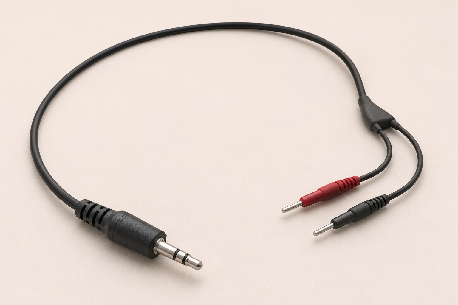
Specify a 3.5 mm plug on the equipment side and 2 mm pins on the electrode side. Send your drawing to review connector fit, cable layout and heavy-duty requirements before requesting a quote.
Check Both Connector Interfaces
For a finished TENS or EMS device, check the model’s approved pad and lead combinations. The TENS and EMS electrode pad compatibility guide explains how to distinguish a pad-side pin socket, snap and direct device mount.
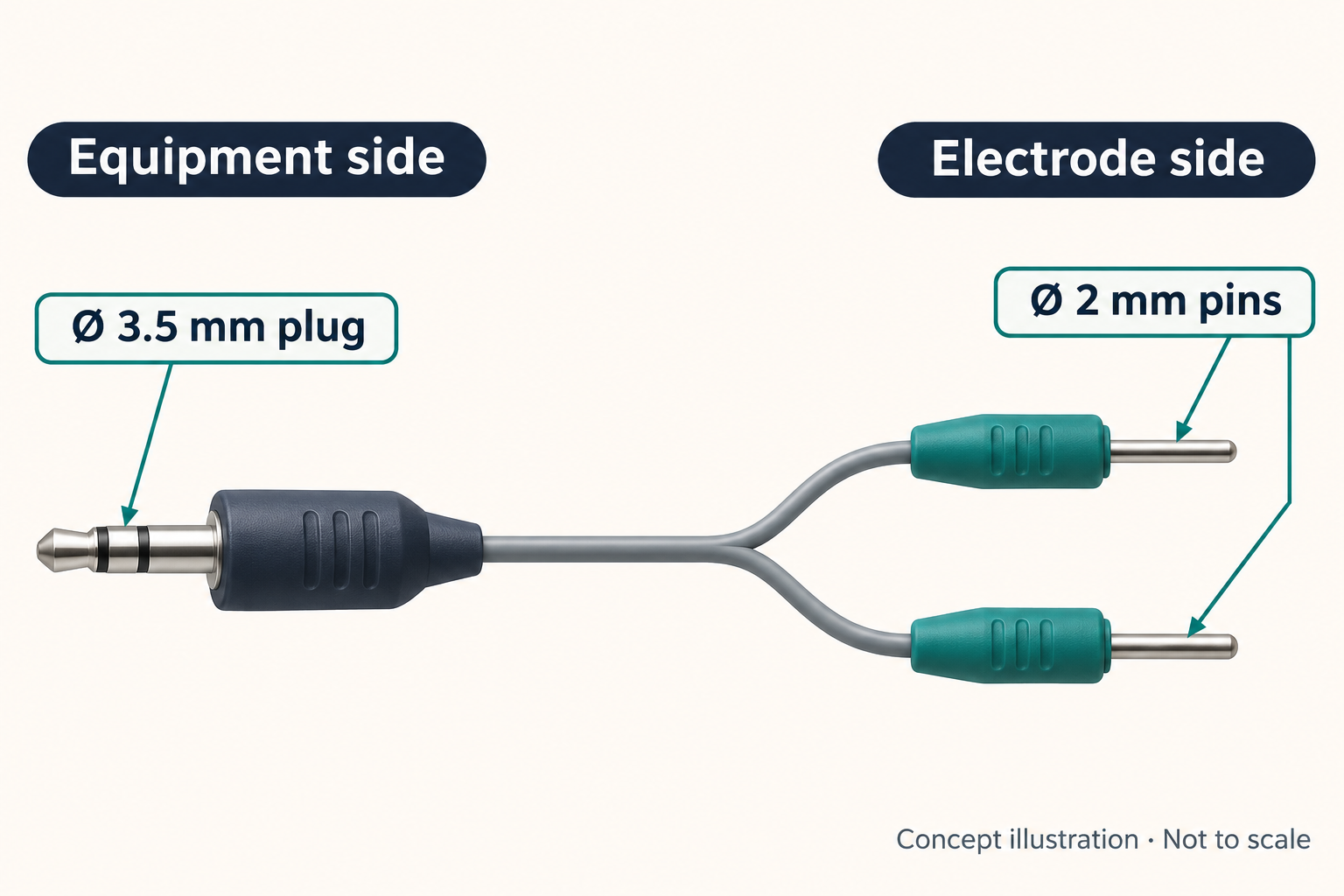
Equipment side · 3.5 mm plug
Specify the mating socket, plug profile, contact count and pinout. Include the available clearance if the socket is recessed or the cable must exit at an angle.
Electrode side · 2 mm pins
Confirm pin quantity, exposed length and mating depth. The 2 mm dimension refers to the pin diameter. Specify the number of pins and branch layout separately.
Specifications to Confirm Before Quoting
Use these fields to describe the assembly you need. MOOSEN reviews the requested configuration and acceptance requirements against your drawing or sample.
Connector layout
3.5 mm plug geometry and pinout, 2 mm pin count and mating dimensions, and terminal identification.
Cable dimensions
Overall length, individual branch lengths, cable diameter and available routing clearance.
Materials and finish
Conductor, insulation, outer jacket, strain relief, markings and packaging where required.
Heavy-Duty Requirements and Inspection
For cables that will be flexed, pulled or connected repeatedly, identify the load points at the plug, branch and pins. Include the test setup and pass criteria you want reviewed for the project.
Repeated flexing
Specify bend location, radius, load and target cycles.
Terminal retention
Specify the pull force, test direction and acceptable movement.
Electrical checks
Provide the pinout and continuity or resistance acceptance criteria.
Record the Two Mating Parts as Separate Interfaces
A 3.5 mm to 2 mm pin lead can put a nominal 3.5 mm plug at the equipment end and nominal 2 mm pins at the electrode end. The number associated with each connector describes a different feature. For a drawing-based order, provide the approved equipment receptacle and the electrode socket or a controlled mating drawing for each side. The quote can then address the connector construction and the cable assembly as one part.
At the equipment end, show the plug diameter, insertion length, contact spacing or contact arrangement and the envelope around the molded body. If the equipment receptacle is recessed, include the opening dimensions and how far the plug body can enter before it contacts the housing. Name the part that the cable must fit. Two equipment plugs can share a nominal diameter and still differ at the shoulder, contact layout or insertion depth.
At the electrode end, define the pin dimensions, contact plating or finish if required, and retention characteristics against the approved socket. Identify how the pin is protected when the cable is handled. If the assembly uses multiple branch ends, show which leads terminate on each branch and specify whether the two pins are identical. The TENS/EMS replacement pad guide helps identify whether the existing appliance uses a pin, snap or separate direct-attach accessory.
Dimension the Main Cable, Split and Branches
Define where each length starts and ends. An overall length measured from the tip of the equipment plug can differ from a length measured from its shoulder. At a Y-split, indicate the distance from the equipment connector to the branch point and the separate reach required at each electrode end. If one branch should be longer for routing, identify it in the drawing and give its tolerance.
Include the allowable jacket size, wire construction and insulation requirements. The cable may need to route through an opening, move around a molded feature or be retained under a clamp. Mark any diameter or bend constraints tied to those interfaces. A sample with the correct free length may still be difficult to install if the connector housing, strain relief or split section exceeds the available space.
Where the cable connects to two electrode sockets, label the branches in accordance with the design. If color, molded markings or labels distinguish the branches, state the requirement for appearance and durability. A dimensional layout with clear branch identification gives both receiving and assembly teams a way to verify that the right lead is being connected to the right location.
Translate Heavy-Duty Lead Wire Into Testable Requirements
Heavy-duty is a procurement description that should be backed by the performance needed at the application. Identify what is expected to resist handling, such as the jacket, the equipment plug, the electrode pins, the strain relief or the branch split. Describe where the assembly is pulled, bent or repeatedly connected. The supplier can then review which mechanical features the drawing should control.
To compare candidate leads, define the mechanical test setup. For an axial pull requirement, identify where the assembly is held, where load is applied and what result qualifies as acceptable. For bending, indicate the location, bend geometry, cycle requirement and inspection criteria agreed for the part. If continuity must be measured during or after the test, say which circuit is monitored and which result is expected. A test definition allows comparisons across samples more reliably than a durability label.
Check the physical interface after the agreed mechanical checks. A lead that meets a conductor continuity requirement may still need inspection for connector movement, damaged insulation or visible separation at the strain relief. Agree which tests apply to qualification samples and which checks belong in the production release record. If the customer provides a mating part or test fixture, identify its revision so a later evaluation repeats the intended setup.
Use a Wiring Schedule and an Acceptance Sample
Show the circuit path from each equipment contact to the corresponding electrode pin. If the equipment-side plug includes more contact positions than the cable uses, mark unused positions clearly. Include continuity checks for each used path and identify which unintended connections the inspection should exclude. The schedule supports wiring review and makes a first-article report easier to compare with the drawing.
For a proof sample, request the termination, cable length and branch layout that the application will use. Submit the required quantities separately if some samples are intended for mechanical verification and others for assembly fit. Record the equipment and pad-side mating references used during the check. A drawing note can list the accepted alternatives when the buyer uses several approved mating parts with the same cable.
Use the purchase item number and revision in the packaging and inspection request. If a replacement version changes only the branch marking, connector profile or length, give that version a clear identifier. This protects the relationship between the delivered lead and the device variant it was ordered to support. Other drawing-defined wiring options are described on the medical wire assembly page.
Send the Requirements Needed for a Comparable Quote
For a prototype order, give the current drawing and the main question the sample must resolve. It may be plug engagement, lead routing, cable handling or the appearance of a particular termination. Include the expected number of trial pieces and the inspection evidence needed. This helps the review focus on the part configuration and acceptance criteria the buyer actually intends to evaluate.
For a repeat purchase, include the anticipated order pattern and packaging quantities. State whether inspection needs actual values by lot, a checklist by assembly or an agreed sampling plan. Discuss the evidence needed for a material or tooling change where it affects the drawing. Record the agreed format with the quotation so later deliveries can be checked against the same release basis.
If the project starts with a legacy lead but no editable drawing, share the available part number, controlled connector dimensions and a list of the characteristics that must match. A photograph can help explain shapes and routing. Dimensions and a wiring schedule are still needed for a formal review. Compare the available electrode lead component options where the requested part has a different device-side or electrode-side interface.
When an equipment plug fits during a trial but the pin layout differs from the drawing, record the physical fit and circuit verification as separate findings. Confirm which contact locations are used and compare each branch with the wiring schedule. A sample with a familiar connector shape can still differ in channel routing or seating depth. If the approved revision calls for a particular branch marking or relief shape, inspect that feature before qualifying the cable for repeat orders. Use a labeled reference sample and a controlled mating drawing so a later change can be compared with the setup used for the original qualification.
Questions Before Quoting
Review both mating interfaces with the equipment or assembly drawing before specifying the lead.
Are the plug and pin diameters enough to confirm fit?
Fit also depends on plug geometry, contact assignment, insertion depth and the electrode connection. Include a mating-part drawing or clear photos of both interfaces.
Can I send photos before I have a drawing?
For an initial review, send clear photos of both connector ends, your target overall length and the number of samples you need. Include a reference part number if available.
What should I include for a heavy-duty cable review?
Describe the expected handling and the areas where the cable bends or carries load. Provide any target flex life, retention force and electrical acceptance criteria.
Send Your Drawing for Review
Share your two connector interfaces, cable length and sample quantity. Attach your drawing or specification when you have it.
Include when available
- Connector drawings, pinout or sample photos
- Overall length, branch lengths and expected annual volume
- Handling conditions, inspection requirements and required records