
SINGLE-CHANNEL FEEDTHROUGH DEVELOPMENT
Hermetic Single Seal Terminals
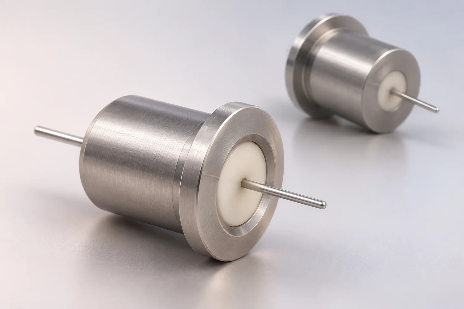
MOOSEN develops compact electrical feedthrough components for sealed medical-device assemblies. For a single-channel terminal, we bring the metal housing, ceramic insulation, fine conductor and joining interface into one drawing-led design review.
One signal path · Ceramic-to-metal interface · Drawing-defined geometry
Published feedthrough experience
MOOSEN documents miniature multi-channel feedthroughs for implantable connections.
Defined material platform
Titanium alloy, alumina ceramic and Pt–Ir conductors appear in the cataloged family.
Precision component work
Small metal parts, joining interfaces and component inspection inform development.
Project-specific acceptance
Sealing and electrical criteria are established for the approved terminal design.
THE COMPONENT ROLE
One electrical path through a sealed boundary
A hermetic single seal terminal carries one conductor through a metal enclosure while electrically separating that conductor from the housing. The seal boundary is created by the selected metal, insulator and joining process; its performance has to be verified on the finished configuration.
MOOSEN’s published miniature feedthrough uses a titanium-alloy shell, alumina ceramic insulation and platinum–iridium signal conductors. A one-channel terminal is a drawing-specific development format based on this feedthrough experience, not a claimed stock model.
Single conductor
A focused path for one electrical connection through the device enclosure.
Compact package
The shell, flange and pin geometry are coordinated with the available assembly space.
Sealed interface
The critical boundary is reviewed together with electrical isolation and joining access.
ENGINEERING CAPABILITY
Hermetic single seal terminal architecture
MOOSEN develops the terminal as a complete electrical interface. The following features guide component engineering against the device drawing and manufacturing route.
Metal housing
The cataloged feedthrough platform uses titanium alloy. Shell diameter, flange and attachment features are adapted to the enclosure interface.
Ceramic insulator
Alumina separates the conductor from the housing and contributes to the sealed material boundary.
Fine conductor
Platinum–iridium is documented in MOOSEN’s feedthrough family; pin size and end form are selected for the electrical connection.
Joining surfaces
The sealing and external connection surfaces are reviewed with assembly access, handling and inspection in mind.
CONFIGURATION
Single seal terminal design options
These are development options, not fixed catalog specifications. Geometry, materials and acceptance are confirmed for the customer-controlled assembly.
| Design area | MOOSEN approach |
|---|---|
| Terminal format | Single-channel, drawing-defined housing and pin geometry |
| Housing material | Titanium-alloy platform documented in MOOSEN’s miniature feedthrough family |
| Insulation | Alumina ceramic platform; final grade and geometry subject to design review |
| Conductor | Pt–Ir option from the cataloged family; final conductor form is project-specific |
| Mounting interface | Flange, shoulder or other enclosure attachment features to approved drawing |
| Hermetic acceptance | Leak method and limit established for the specific assembly |
| Electrical verification | Continuity and insulation checks defined for the intended connection |
DEVICE INTEGRATION
Where a single-channel terminal can fit
A single electrical path can simplify a focused connection point in a sealed package. MOOSEN engineers the terminal around its mating materials and downstream assembly requirements.
Active device enclosures
A feedthrough path between a sealed electronics compartment and an external connection, subject to device-level design and validation.
Compact sensor packages
A single insulated conductor where the enclosure boundary and signal path must be considered together.
Electrode interface modules
A precision terminal concept that can be assessed alongside MOOSEN’s electrode contact and feedthrough-related component experience.
MOOSEN EXPERIENCE
Feedthrough know-how backed by precision component work
MOOSEN’s cataloged miniature feedthrough brings together titanium alloy, alumina and Pt–Ir conductors for sealed electrical transmission. Its configurable pin arrangement provides a relevant engineering starting point for a one-channel package. The single seal format shown here remains a project-specific concept until its construction and performance are qualified.
From material to interface
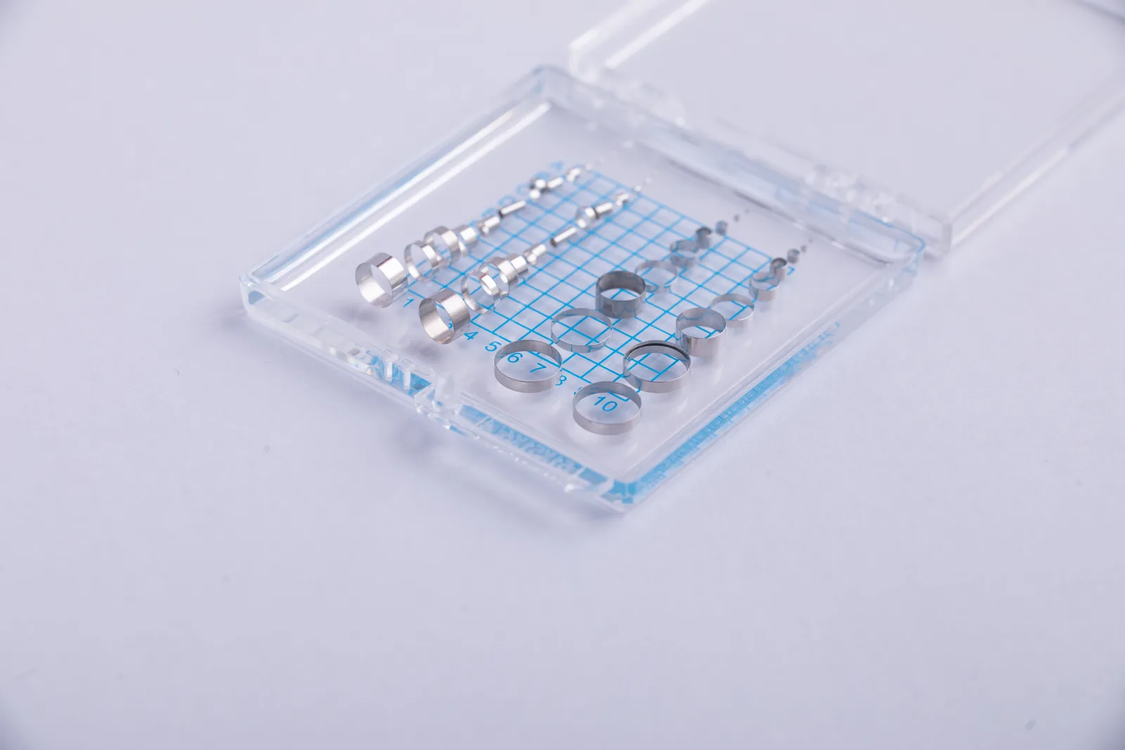
MOOSEN works with small metal parts and precious-metal conductors that must fit a larger device assembly. For a single seal terminal, the team can align material choice, conductor handling, joining access and enclosure fit early in development.
Inspection around critical features
Visual and dimensional checks support small-part consistency. Hermetic and electrical test methods are selected for the approved terminal configuration rather than assumed from another design.
Select the right component for your assembly
Compare how each terminal locates one conductor relative to the wall and the internal connection point. Use the drawing to distinguish each terminal version, even when it fits the same machined opening. The terminal dimensions, joining interface and single-conductor inspection scope are reviewed with the installation drawing.
| Component route | Choose it when | What to confirm |
|---|---|---|
| Hermetic single seal terminals | one electrical path across a sealed package boundary | Use the approved drawing and assembly method as the decision basis. |
| Hermetic rectangular connectors | multiple contacts must be arranged in a rectangular package | Review this component |
| Medical hermetic feedthrough components | the feedthrough geometry is still open | Review this component |
Prepare a useful RFQ
Send a section of the wall and the terminal showing the design revision and the seating depth. The contact form accepts a wall section and terminal detail, including joint geometry and the verification required for sample and recurring lots.
- package geometry
- Pt–Ir conductor
- mating interface
- seal test method and acceptance criteria
Evidence to agree: the conductor designation, seating dimensions, insulation test points and leak test results for the agreed terminal boundary. A single terminal’s usable dimensions and checks depend on the conductor, insulator and installation joint.
FREQUENTLY ASKED QUESTIONS
Locate one conductor at the housing wall
A hermetic single-seal terminal gives one conductor a defined passage through the enclosure. Start with a section through the terminal and wall. Locate the opening from the assembly datums and show the wall thickness, terminal body diameter and seating depth. Define the fit between the terminal body and the opening, including any shoulder that positions the part during assembly. Show the joint that seals the body to the wall and identify the surfaces that must remain accessible while that joint is made.
Dimension the exposed conductor on both sides from a reproducible face. Check pin projection against the space needed for the mating part, lead attachment or assembly tooling. Where several single seals share a wall, dimension their center spacing and specify minimum separation from nearby conductors and grounded metal. Include any positional tolerance that limits that separation. If several circuits must enter through a common opening, compare the arrangement with a hermetic rectangular connector or medical hermetic feedthrough assembly.
Specify the pin alloy and termination on each side
State the exact conductor material and any finish, and show which portion of the conductor passes through the insulator. Platinum-iridium is used in some hermetic feedthrough designs. For a MOOSEN inquiry, specify it where the drawing calls for it and include the required grade or composition. Review the conductor, insulator and terminal body as a material combination. The planned downstream joining process and any finish restrictions belong in the same review. See SCHOTT feedthrough material examples.
A rigid pin has a defined diameter and projection for a board, contact or other localized termination. If the assembly needs a flexible lead, state whether you want it supplied as part of the component or attached during assembly. Give the lead material, length and routing, and show where it joins the sealed conductor. Include any strain-relief feature and tell the supplier which side of the terminal will be accessible when making that connection.
Define the checks for the terminal and installed joint
For fit inspection, identify the seating diameter, shoulder position, exposed conductor length and any electrical separation that needs measurement. Specify the continuity points and conductor-to-body insulation checks that apply to the design. For leak testing, give the acceptance limit with units, method and test conditions. Identify whether the report must cover the terminal alone, the terminal joined to a representative wall or the finished enclosure. If welding or another step follows the incoming test, specify any checks required afterward.
When the terminal is supplied loose, show how your first-article fixture will reference the part during measurement. An axial reading taken from the end of the body can differ from a reading taken from the shoulder that seats against the wall. Define the datum on the drawing and tell the supplier if the result needs to be reported as an actual value. For lot identification, choose a label that remains associated with the pin material, body geometry and revision through receiving.
If several similar versions differ only in pin length or material, identify each individually and show the corresponding mating requirement. Discuss lot separation where mixed pieces are difficult to recognize visually. For a sealed interface near another circuit, state the distance or electrical test that governs acceptance. Mark the side of the terminal that faces the internal volume so assembly and inspection refer to the same orientation.
Send the current drawing, material callouts and inspection requirements for a single-seal terminal review. Include a section of the host enclosure if the terminal geometry is already defined by the existing opening or mating part.
Hermetic single seal terminal FAQs
Does MOOSEN have a standard single seal terminal?
MOOSEN’s published catalog shows miniature multi-channel feedthroughs. A one-channel terminal is presented here as a drawing-led development direction, not as a verified stock part.
What material system informs the design?
The documented feedthrough family uses a titanium-alloy shell, alumina ceramic insulation and platinum–iridium conductors. Final materials for a single terminal are confirmed against the application.
Can the housing and pin geometry be customized?
The enclosure interface, conductor ends and mounting features can be reviewed against a customer drawing. Feasibility is confirmed before a configuration is offered.
How is the hermetic seal verified?
A project defines its own leak-test method, acceptance limit and inspection scope. The performance of the published multi-channel product is not automatically applied to a new single-channel design.
Is the terminal a finished medical device?
No. MOOSEN supplies components for integration into customer-controlled products. The device manufacturer is responsible for finished-device validation and regulatory decisions.
Can the pin and housing dimensions match our package?
MOOSEN manufactures drawing-defined terminal components for the specified pin count, housing geometry and joining interface after a feasibility check.
Can we order samples for seal-process validation?
MOOSEN can quote component samples for the customer’s joining and leak-test trials. Final hermetic performance belongs to the qualified package assembly.
CONNECT WITH MOOSEN
Develop a focused sealed connection
Send your one-channel feedthrough drawing. MOOSEN can define the conductor and terminal component scope around the enclosure interface and specified material stack.