
PLATINUM–IRIDIUM · ELECTRICAL CONTACTS
Platinum Iridium Electrode Rings
MOOSEN develops drawing-based Pt–Ir ring contacts for customer-designed sensing and stimulation assemblies. Exposed contact geometry, conductor connection and insulation interfaces are engineered together for the specified device construction.
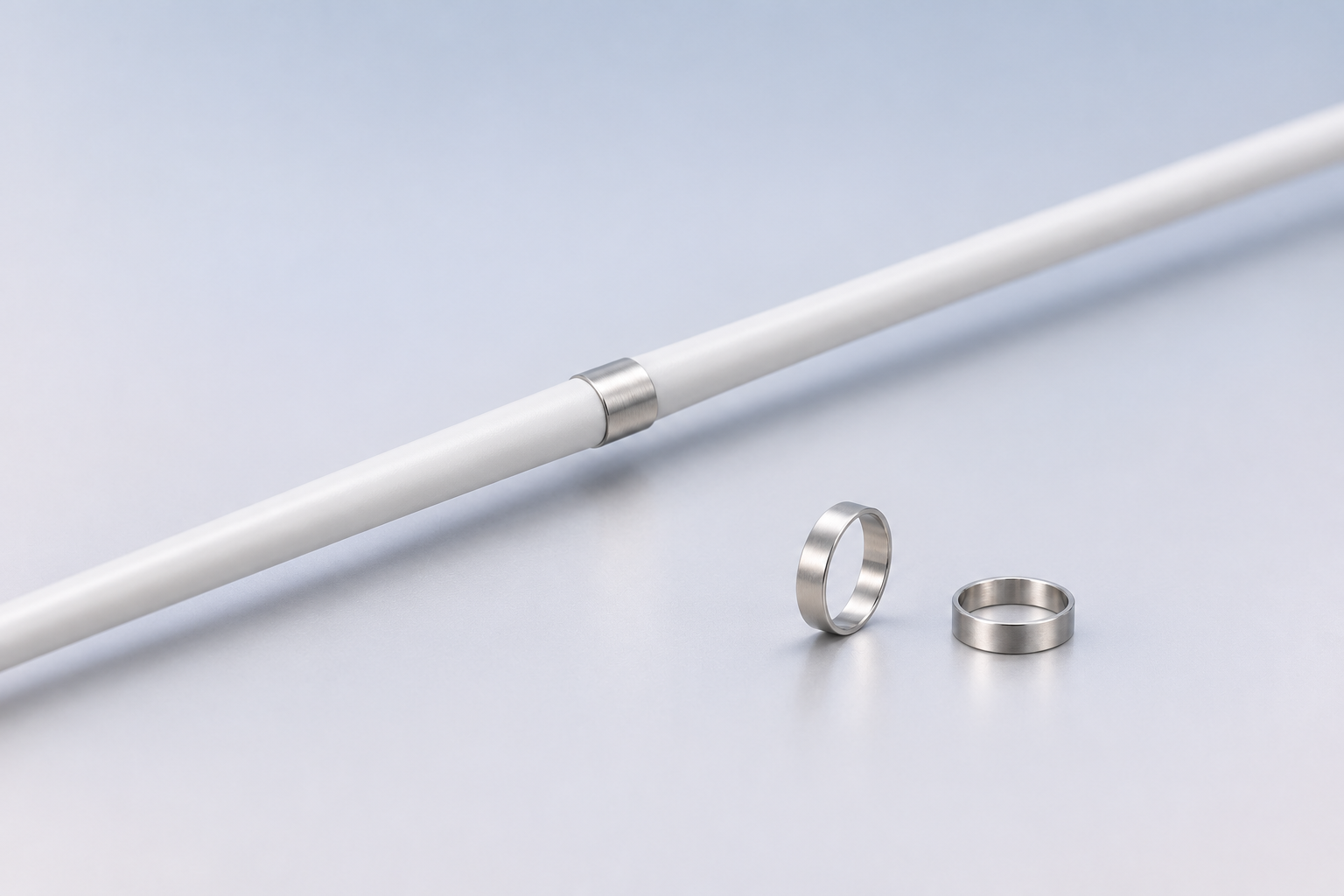
Pt–Ir components
Electrode rings within a wider precious-metal portfolio
Contact geometry
Exposed area and ring form considered together
Lead integration
Fit with insulation, shaft and conductor
Inspection
Critical features defined by the approved drawing
ELECTRODE CONTACT FUNCTION
A ring designed around the electrical interface
An electrode ring is a compact metal contact used within a customer-designed lead, catheter or other medical-device assembly. Its useful design depends on more than the alloy: the contact surface, mating conductor, insulation boundary and attachment process all affect the component definition.
MOOSEN supports Pt–Ir ring forms for medical-device programs and works with device teams to align material, geometry and inspection with the approved component drawing. For rings used primarily for X-ray position marking, see our platinum iridium marker rings.
MOOSEN CAPABILITIES
Precision ring components for lead and catheter programs
Drawing-defined form
OD, ID, width, wall, edges and special features are reviewed against the device envelope.
Assembly interface
Ring geometry is considered with the conductor connection, insulation and intended joining route.
Component verification
Visual, dimensional and applicable electrical checks are defined for the approved project scope.
APPLICATION EXPERIENCE
Electrode contacts in device assemblies
MOOSEN’s Pt–Ir component work includes ring elements alongside fine spring wire in an anonymized neuromodulation program. Related electrode-contact forms can be reviewed for electrophysiology, sensing and stimulation assemblies according to the customer’s drawing and device design.
MOOSEN supplies components for integration into customer-controlled medical devices. Finished-device validation remains with the device manufacturer. Learn more about our Pt–Ir precision component portfolio and quality approach.
TALK WITH MOOSEN
Request an electrode ring quotation
MOOSEN engineers Pt–Ir material form, ring geometry and conductor interfaces to your drawing, with an agreed inspection approach for the component order.
Electrode ring specification and interface
Electrical-contact intent makes this page different from a radiopaque marker-ring page. An electrode ring must be assessed as an exposed conductive surface within an insulated and connected assembly.
| Material | Platinum–iridium grade and condition per approved drawing |
| Ring form | OD, ID, width, wall thickness and tolerance stack |
| Contact surface | Exposed area, finish and edge condition |
| Connection | Conductor attachment and allowable heat or forming exposure |
| Insulation interface | Location of the exposed contact relative to the shaft or lead insulation |
| Verification | Dimensional, surface and applicable electrical checks agreed per program |
How MOOSEN supports electrode-contact development
Device interface review
Ring geometry is considered with the mating conductor and insulation boundary.
Manufacturing route
The component process is planned around miniature Pt–Ir form and assembly needs.
Project-specific evidence
Critical features and records are defined with the customer’s drawing and test method.
Select the right component for your assembly
Compare adjacent MOOSEN component forms by function and interface. These are design routes, not interchangeable stock sizes. Final feasibility, dimensions and acceptance are reviewed against your drawing.
| Component route | Choose it when | What to confirm |
|---|---|---|
| Platinum–iridium electrode rings | an exposed contact in a lead or catheter assembly | Use the approved drawing and assembly method as the decision basis. |
| Platinum–iridium marker rings | radiographic position marking is the primary purpose | Review this component |
| Implantable contact modules | a larger mating/contact module is required | Review this component |
Prepare a useful RFQ
Please include the current drawing revision and the fields below where available. The contact form accepts a drawing or specification file; prototype quantity, annual volume and required records can be added there.
- exposed contact area
- ring ID/OD and width
- conductor joint
- insulation boundary
- surface and electrical checks
Evidence to agree: material documentation, critical dimensions, visual or electrical checks, sampling and release records as applicable to this component. No universal size, tolerance or performance claim is implied.
Draw the conductive ring in the shaft and casing
Show the ring in a longitudinal section through the shaft and in an end view through the conductor. Identify inside and outside diameters, axial length, edge breaks and adjacent casing or jacket locations. The end view can show the ring relative to a lumen, conductor channel or joining opening. Dimension minimum clearances from the locating features. If the ring has a registration feature, give its angular position relative to the conductor channel and identify which face is distal.
Put the exposed conductive length on the assembly drawing. A metal ring can extend under the casing at either end, giving it an overall length and a shorter exposed length. Show where each casing edge should stop, the allowable axial movement and the permitted step between metal and surrounding material. If the ring is exposed around part of its circumference, include a view that shows the boundary. These views let the assembler and inspector refer to the same exposed region.
For multiple contacts, number the rings from a defined reference end and carry those identifiers into the wiring diagram. Define the gap between adjacent exposed surfaces in addition to a center-to-center locating dimension. Variation in that gap can come from metal position or casing position. Inspect the contributors separately where the exposed gap has its own acceptance limit.
Specify where the wire joins the ring
Locate the joint inside the ring, at an edge or within a recess as required. Show the approach of the wire and allowable joint profile after joining. An inside connection uses space between ring and shaft, where extra height can interfere with fit or crowd insulation. An edge connection may need clearance from the next contact or casing seam. Indicate which surface stays clear of joining material and identify the exposed conductor length at the joint.
For loose rings, confirm which features must be ready for downstream joining. For rings delivered with a wire attached, give wire material, reachable test points and allowable wire exit position. Include a section showing where the casing supports the lead and where it bends. A wire evaluated straight on a bench can load the joint differently once routed through the shaft.
Check the assembled contact and incoming parts
For a joined assembly, assign each ring to its connector pin and specify the check between that pin and ring. State probe locations and resistance or continuity acceptance. If adjoining rings must be isolated, identify the test pairs and condition of the assembly. The pin-to-ring check assesses the conductive path. Impedance at the exposed interface requires a separate measurement setup. See the FDA example of connector-to-contact testing.
For incoming rings, identify the drawing and material specification, inspection lot and sampling requirements. Agree which dimensions are taken on the free ring or in a fixture, especially where a thin wall can move during gauging. Control the conditions where visual limits apply to burrs, dents or scratches. Ask for reports that reference drawing feature numbers. Where a drawing invokes a dimensioning standard, name its edition. See ASME engineering drawing standards and MOOSEN quality information.
On a first build, inspect the ring after the casing and conductor reach their final positions. Compare exposed length and surface step with the drawing and record the contact test against the same identifier. If the casing is bonded or reflowed after wiring, state whether a check is required before, after or at both stages. This helps trace a change to the operation that introduced it.
Ask how the receiving label will distinguish parts that share the same external diameter. A ring with a different bore or joining opening can resemble the original part in a tray. The package label, part drawing and inspection record should refer to the same revision. Define how sample parts used for destructive checks will be distinguished from parts intended for assembly evaluation.
Choose the ring for its function
Use the electrical and dimensional criteria above for a ring connected to a channel. If the part provides an imaging reference, review marker bands and platinum-iridium marker rings. The electrode components guide compares rings with discs, wire-form contacts and electrode leads. Send the ring drawing and shaft and casing sections, with traceability requirements and the desired delivered form.
Define how the contact surface will be protected during handling and transport. A mark on an exposed electrode face can have different acceptance implications from a mark in a region that will be covered. Give the supplier a drawing reference to each functional region and describe the inspection conditions for the surfaces that matter. If rings are loaded in a tray, specify which surfaces can rest against it and which orientation the assembly team needs. That agreement can help keep incoming inspection and placement efficient without obscuring the dimensional acceptance requirements.
If several contacts share a connection method, use the same terminology for their joint regions and label which features differ by channel. A slot, recess or formed edge can alter how the wire seats even when the nominal bore matches. Document acceptance for the altered feature separately so the receiving report can distinguish a material issue from a fit or joint issue.
Platinum iridium electrode ring FAQs
How is an electrode ring different from a marker band?
An electrode ring is specified for an electrical contact function, including surface exposure and conductor attachment. A marker band is specified primarily for visibility under imaging; some designs may combine functions.
Can MOOSEN supply a finished implantable lead?
This page concerns precision components for integration by the device manufacturer. Finished-device qualification remains with the customer.
What should an electrode-ring RFQ include?
Send the ring drawing, Pt–Ir material requirement, conductor and insulation interface, intended joining method, inspection criteria and program volume.
Can the ring ID, width and exposed area match our lead design?
MOOSEN manufactures platinum-iridium electrode rings to customer-defined dimensions and exposed-contact geometry after confirming feasibility.
Can samples be supplied before the full lead is qualified?
MOOSEN can quote ring samples for the customer’s assembly and electrical evaluation, then supply repeat orders to the approved component revision.
What inspection records can be supplied?
MOOSEN defines dimensional, surface and material checks with the buyer and provides the agreed release documentation for the component order.